

Wiring Diagram Needed: HEI + Voltmeter, Mercuiser 288 350 SBC
 05-15-2011, 06:29 PM
#1
Registered
Thread Starter
So I have a mercruiser 260, which is a 350 small block chevy. Original date is 1978, and at that time it had a standard distributor, and an ammeter.
In all my schemetics, the output of the alternator goes all the way forward to the front of the boat, into the ammeter, then through the ignition switch. My new gauges have a volt meter, so I'm running a small wire off of the ignition switch. Should be fine, I think. But how does the charging system look? Does the alternator get hooked up the battery or the circuit breaker or what?
Also, since it now has HEI, do I just completely ignore the 'resistence' wire?
 05-16-2011, 01:54 PM
#3
Registered
Thread Starter
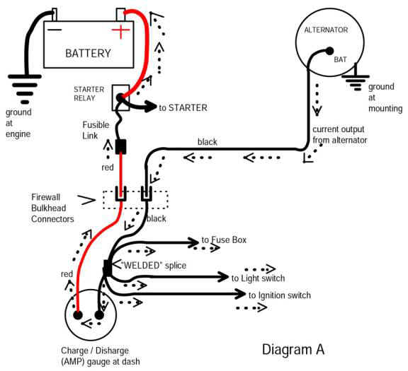
So this is what it basically had before:
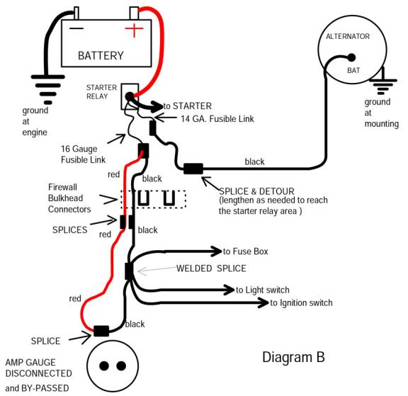
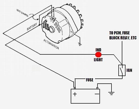
but now that I have a voltmeter, it will be more like this:
What's confusing me is the circuit breaker and starter solonoid.
but now that I have a voltmeter, it will be more like this:
What's confusing me is the circuit breaker and starter solonoid.
05-16-2011, 03:14 PM
#5
Registered
Thread Starter
Yeah, I'm guessing I don't need the resistor wire at all, just leave it disconnected. Just run the "running" position from the ignition key to the distributor. Right?

 05-16-2011, 06:37 PM
#10
Registered
Thread Starter
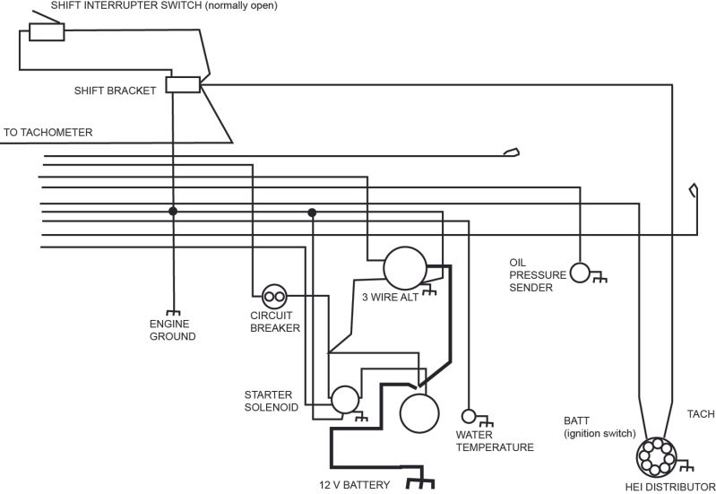
Okay, here is my new schematic. The alternator is a 3 wire, I read that the sensing lead should go to the 12v distribution point, so it maintains 12v at that point. The other wire goes to the alternator warning light, then the ignition switch.
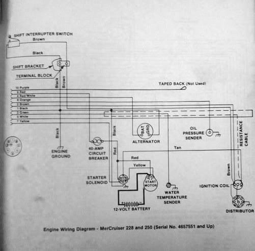
The HEI distributor eliminates the resistence wire, and the two connections are BATT and TACH. The BATT should be from the ignition switch. The tach wire runs to the shift cutout switch, at which point it goes to the actual tach. Here is a pic:
The HEI distributor eliminates the resistence wire, and the two connections are BATT and TACH. The BATT should be from the ignition switch. The tach wire runs to the shift cutout switch, at which point it goes to the actual tach. Here is a pic:

