

Totally confused need help
 07-22-2021, 08:28 PM
#1
Registered
Thread Starter
https://www.planetnautique.com/Corre...980/80snwd.jpg
Anybody, any help any explanation is greatly appreciated.
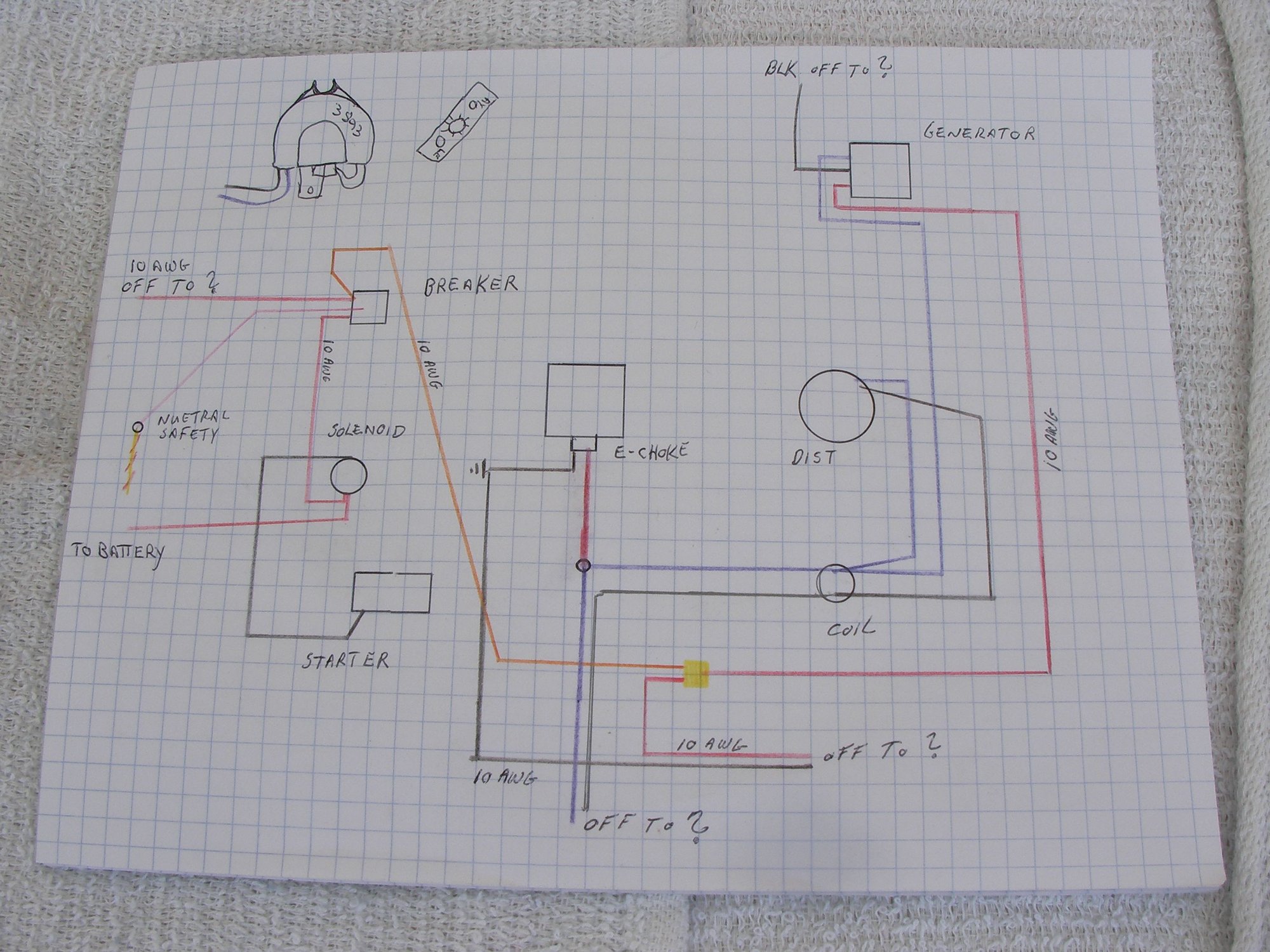
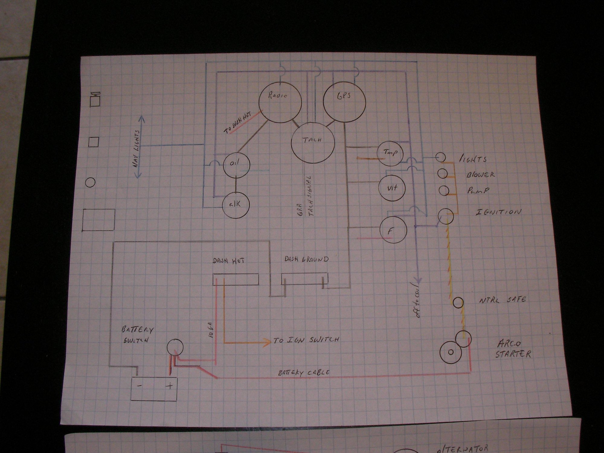
the above link shows 10g red orange and black from the volt meter to the the battery alternator and ground.
the drawing at bottom center shows red and orange spliced together ( it was melted),
this engine was converted from points to electric, a new starter has the solenoid attached and the ballast resistor is no longer needed.
when i draw it out i cant account for the 10g red wire that leaves what i believe is the dash side of the circuit breaker.
i'm thinking; battery to switch to starter (big battery wire), from switch to breaker to dash hot terminal, from terminal to ignition switch.
from ignition to gauges purple and the yellow w/red to starter solenoid.
The diagram shows no purple to volt meter, do i really run 3 10g orange from alternator to "I" on voltmeter
and 10g red from "s" on volt meter to battery ? Can it be to a hot terminal under the dash?
can the 10g ground go to a ground terminal under the dash.
why is there a wire from breaker to solenoid and where does the 10g red wire that leaves the breaker go to.
i know it was hacked at some point, i have all new harnessess engine- boat- dash, there is only 1 10g red and black in that harness, no orange and certainly no 10g orange.
the harness assembly and starter came from a specialty shop they are both specifically for this engine, the starter came with wires and detailled directions to splice into the original harness which is long gone.
all the schematics ive looked at do not help, in fact a later model electric ignition volt meter is wired purple black and blue for lights like all the other gauges.
you ever take on a boat project, for Gods' sake buy a clean take out engine that only needs to be plugged into the correct harness and not un big jimbo'd up spliced together melted electrical tom foolery.
Anybody, any help any explanation is greatly appreciated.
the above link shows 10g red orange and black from the volt meter to the the battery alternator and ground.
the drawing at bottom center shows red and orange spliced together ( it was melted),
this engine was converted from points to electric, a new starter has the solenoid attached and the ballast resistor is no longer needed.
when i draw it out i cant account for the 10g red wire that leaves what i believe is the dash side of the circuit breaker.
i'm thinking; battery to switch to starter (big battery wire), from switch to breaker to dash hot terminal, from terminal to ignition switch.
from ignition to gauges purple and the yellow w/red to starter solenoid.
The diagram shows no purple to volt meter, do i really run 3 10g orange from alternator to "I" on voltmeter
and 10g red from "s" on volt meter to battery ? Can it be to a hot terminal under the dash?
can the 10g ground go to a ground terminal under the dash.
why is there a wire from breaker to solenoid and where does the 10g red wire that leaves the breaker go to.
i know it was hacked at some point, i have all new harnessess engine- boat- dash, there is only 1 10g red and black in that harness, no orange and certainly no 10g orange.
the harness assembly and starter came from a specialty shop they are both specifically for this engine, the starter came with wires and detailled directions to splice into the original harness which is long gone.
all the schematics ive looked at do not help, in fact a later model electric ignition volt meter is wired purple black and blue for lights like all the other gauges.
you ever take on a boat project, for Gods' sake buy a clean take out engine that only needs to be plugged into the correct harness and not un big jimbo'd up spliced together melted electrical tom foolery.
 07-24-2021, 01:32 PM
#2
Registered
Thread Starter
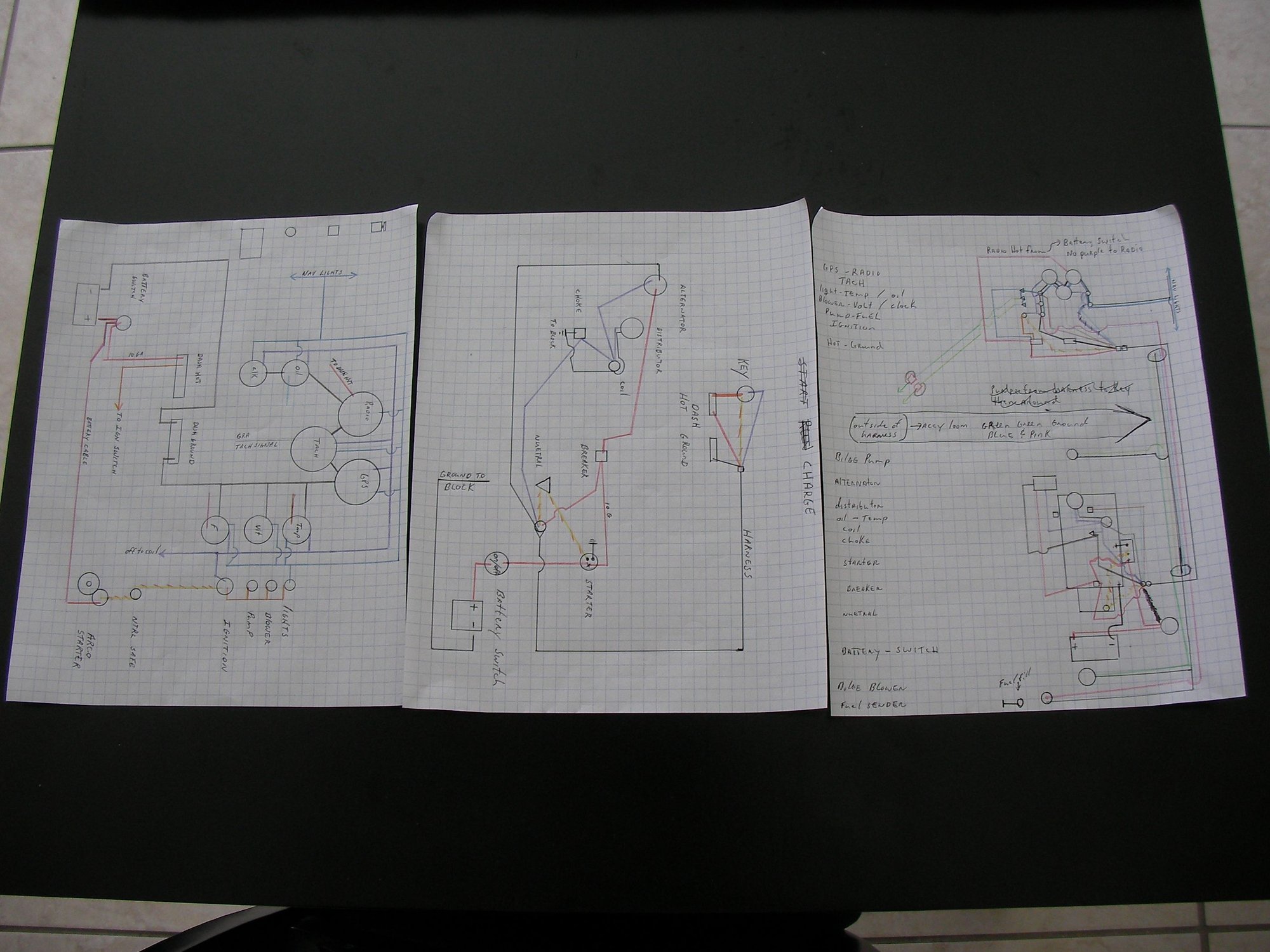
i got some big help over on the ski boat website, swear to God some of those guys are walking tech manuals, and fast, boom here it is !
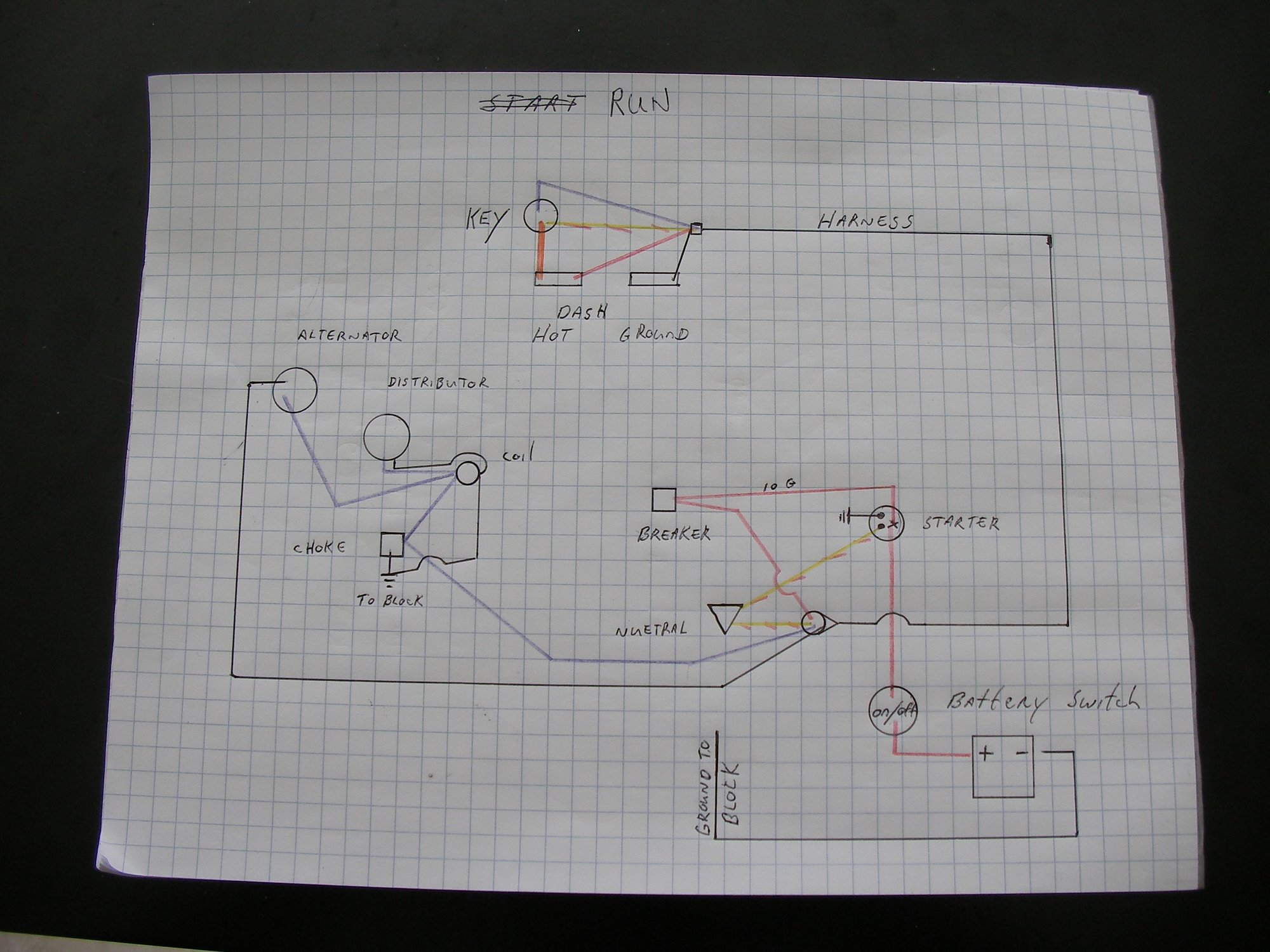
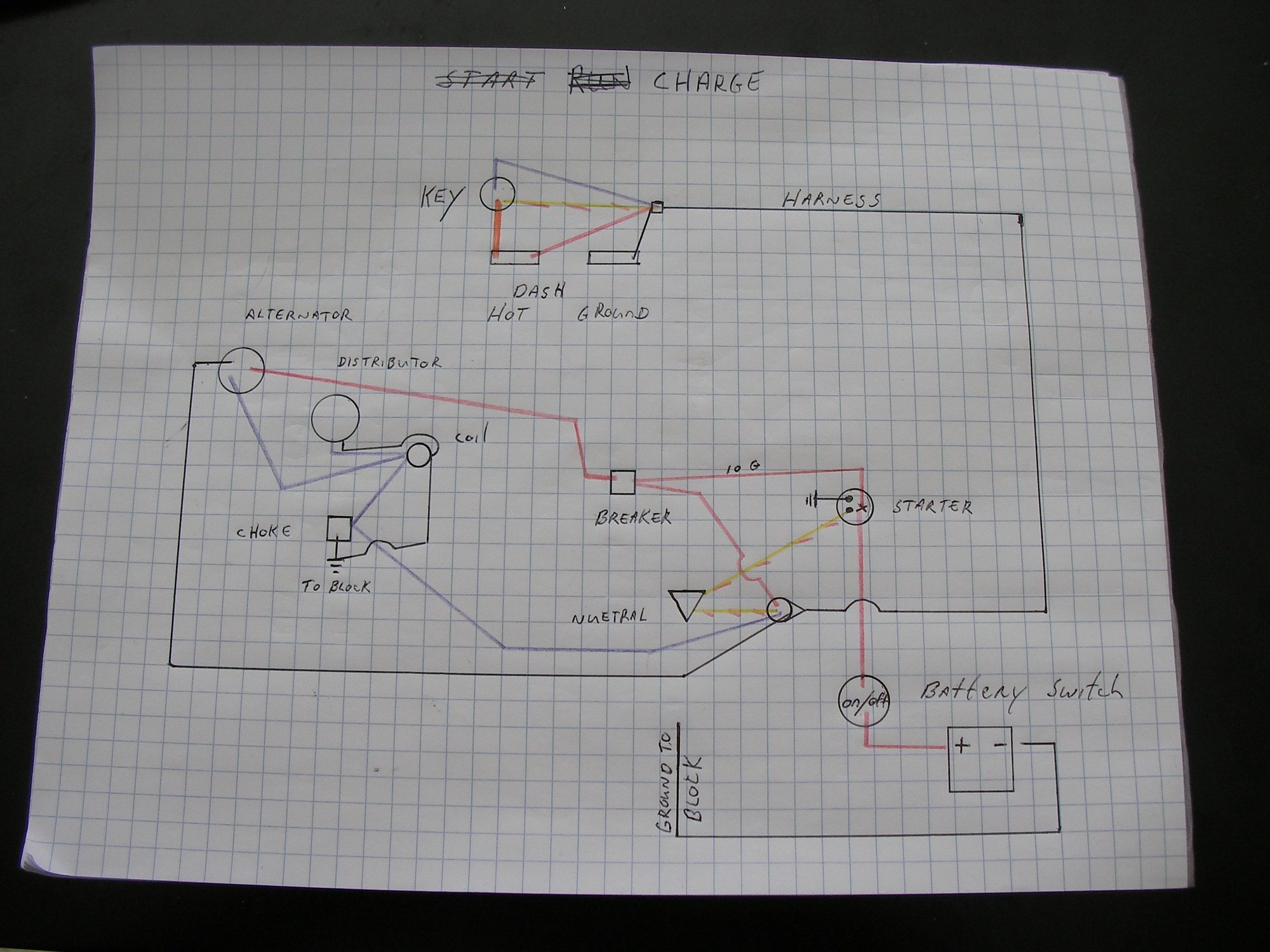
as i understand it the original charging circuit went from alternator to ammeter to key to someplace over the rainbow and eventually reached the battery.
The engine was converted from points to electric, whoever did the conversion ( big jimbo) "wired it to work" so using the original harness regardless of wire color or what could be jumped spliced twisted taped melted or left cut and going nowhere that's what it got.
i'm catholic so electricity, ac or dc, amps ohms volts resistance, the metric, the dash or an and jic fittings and .000's of an inch are nothing but black magic witchcraft and devil numbers, some 12 volt stuff looks like direct shorts, the old points schematic and the new electric schematic didn't match what was on the engine big jimbo.
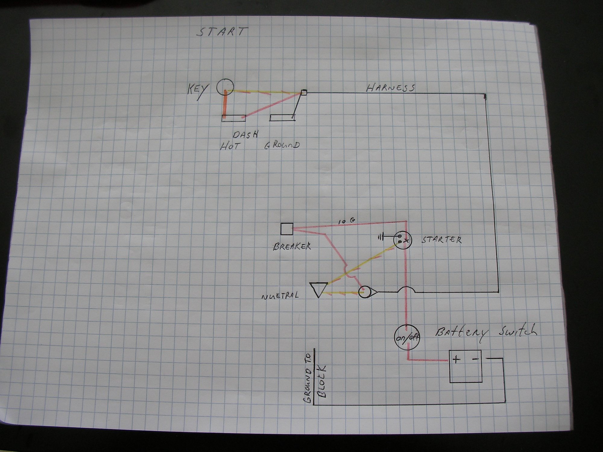
i got start run & charge, backwards behind dash and whole boat overview.
this is points converted to electric, no ballast resistor, no remote solenoid, no splicing jumping or witchcraft
new harness new gauges new starter w/ solenoid attached.
The following users liked this post:
Rookie (07-28-2021)


