

Fountain 47, 2372cid single engine diesel
 02-03-2024, 03:38 PM
#291
Registered
There are no other person than me engineer this boat, lot work to one person.

The following 2 users liked this post by AllDodge:
ksalmine (02-04-2024), Twin O/B Sonic (02-04-2024)
02-04-2024, 07:32 AM
#292
Registered
a while back when you first mocked up and built this split box, i wanted to ask about assembly.
Does the cover have to be installed and removed to shim each gear and a rolling torque performed as each gear is installed to make sure each gear and it's bearings aren't too tight in the case ?
What kind of bearings for each gear ?
straight cut gears right ?
Awesome job as usual, finished project will be a success for sure.
02-07-2024, 07:02 AM
#293
Registered
Thread Starter
Outonsafari, I had think clearance adjustment alot before I found out this solution.
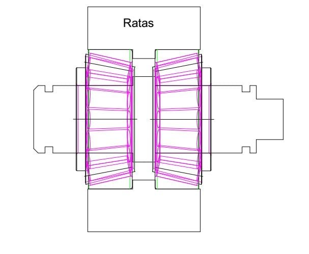
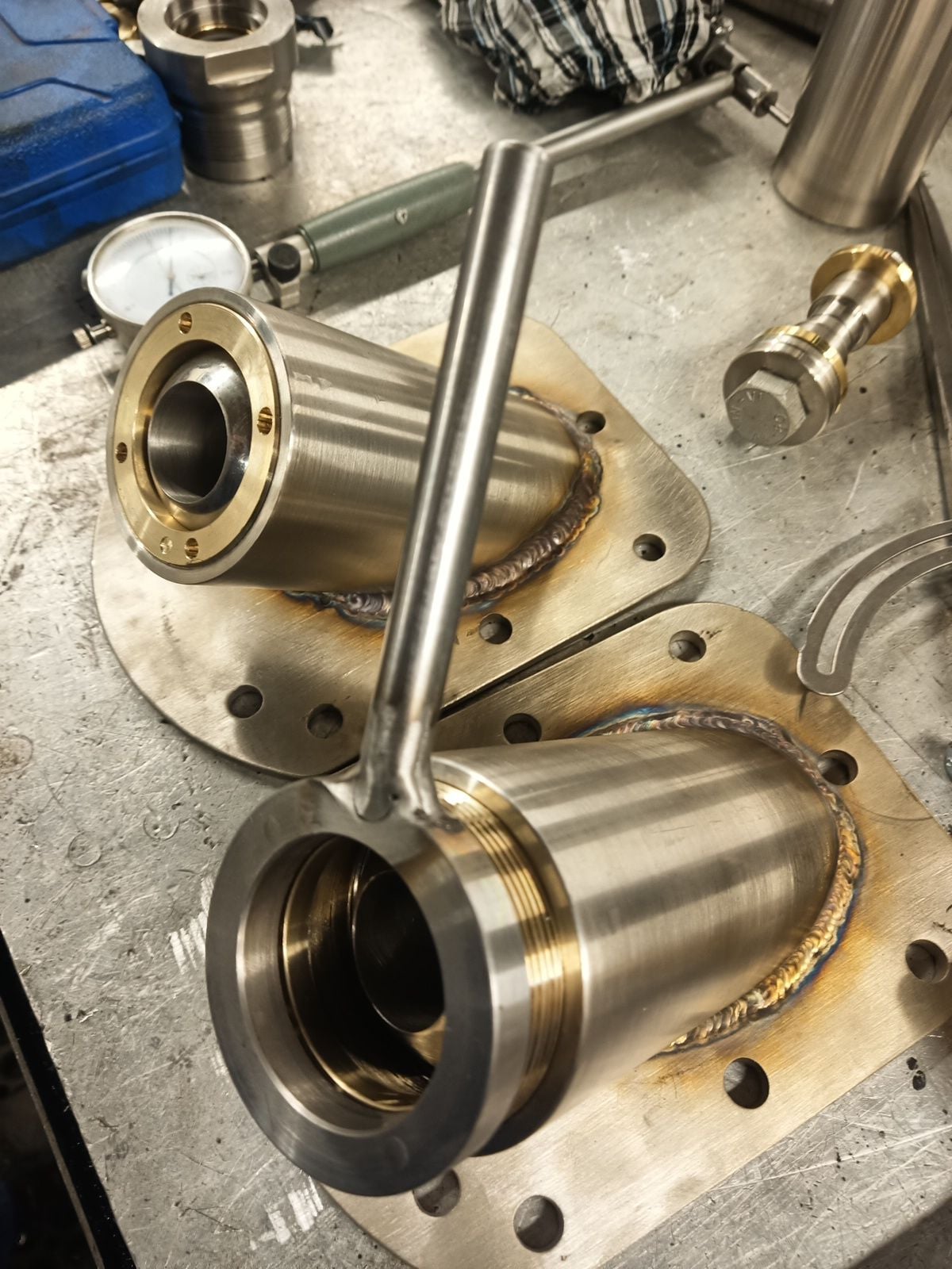
Picture above is intermediate gear, it have tapered roller bearings inside gear so it lighten gear and make less binding force to shaft. Shaft have flange between bearings and each gear-shaft package can be shimmed to zero clearance separate, out from splitbox case. Before splitbox back cover is assembled, I will measure bearing inner race heights and shim 0.1-0.2mm compression. It won't affect to bearing clearance because inner races are solid to each other. Hard to expalin in a foreing language but hope you get it?
I try keep rolling resistance low so no pretightening to bearings, all clearance to zero.
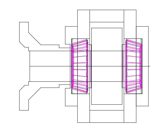
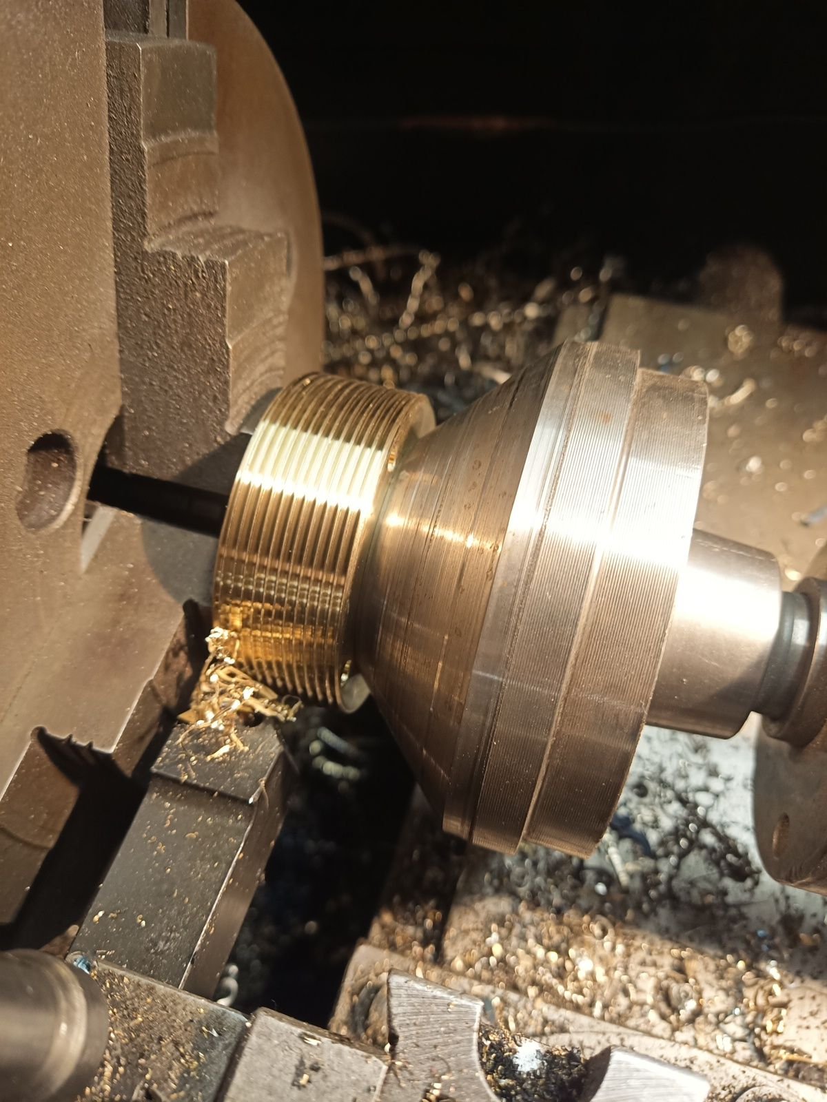
This picture is output shafts. It have bigger tapered roller bearings. Cearance is set by shims under bearing caps. Adjustment will be done after splitbox is assembled.
Gears are module 5, 50mm wide straight cut gears.
Picture above is intermediate gear, it have tapered roller bearings inside gear so it lighten gear and make less binding force to shaft. Shaft have flange between bearings and each gear-shaft package can be shimmed to zero clearance separate, out from splitbox case. Before splitbox back cover is assembled, I will measure bearing inner race heights and shim 0.1-0.2mm compression. It won't affect to bearing clearance because inner races are solid to each other. Hard to expalin in a foreing language but hope you get it?
I try keep rolling resistance low so no pretightening to bearings, all clearance to zero.
This picture is output shafts. It have bigger tapered roller bearings. Cearance is set by shims under bearing caps. Adjustment will be done after splitbox is assembled.
Gears are module 5, 50mm wide straight cut gears.
02-07-2024, 07:30 AM
#294
Registered
Thread Starter
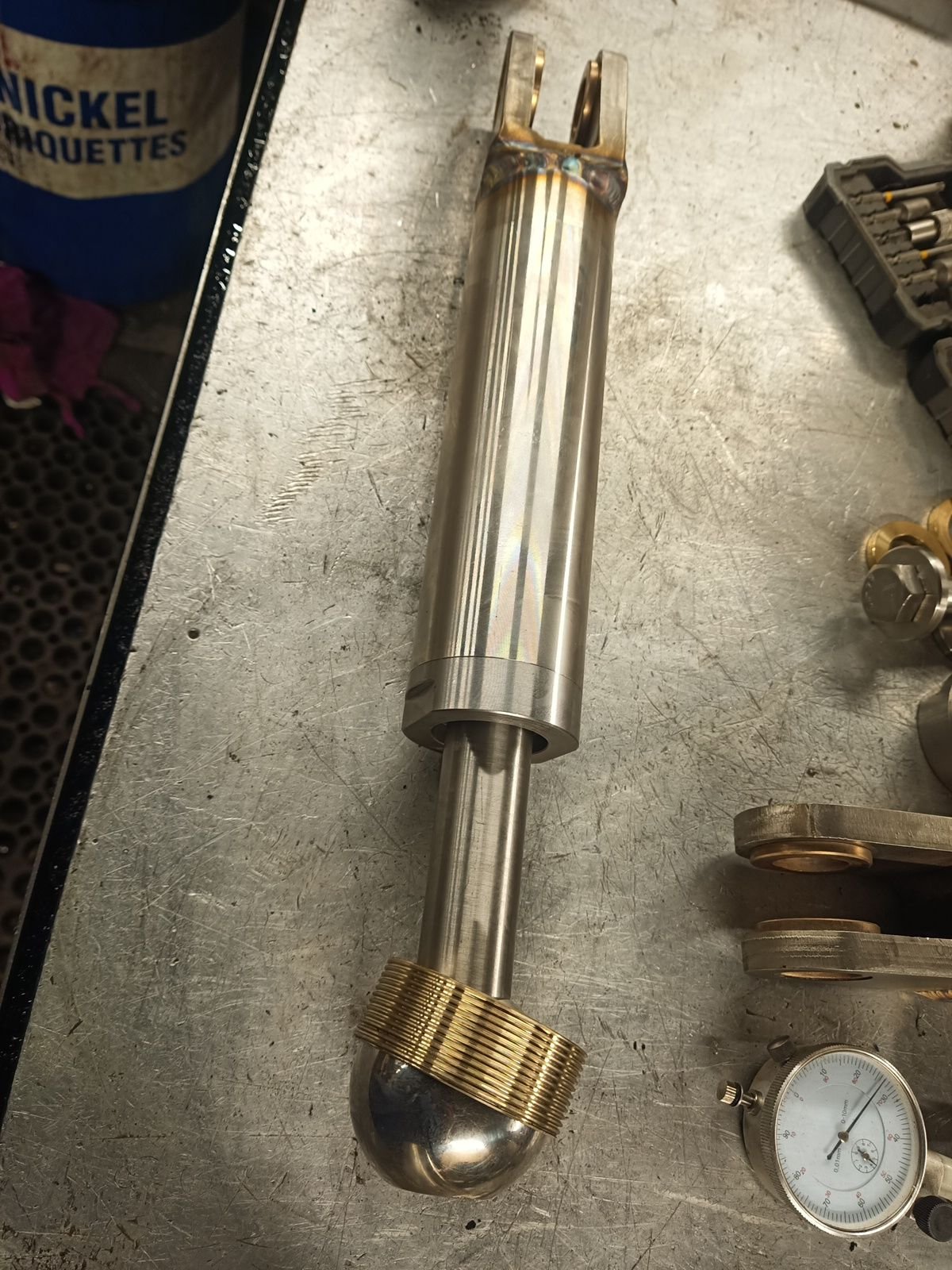
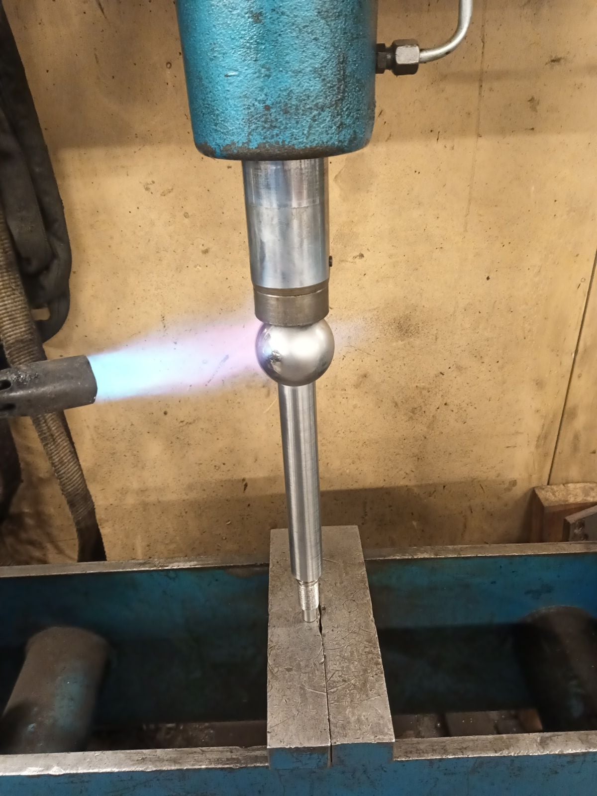
Trim cylinders are almost ready. I made few mistakes but all is now repaired. Tubes was 65mm too long, I screwed up lenght dimension from CAD drawing, complete lenght and tube lenght get crossed.
This time I weld all parts myself.
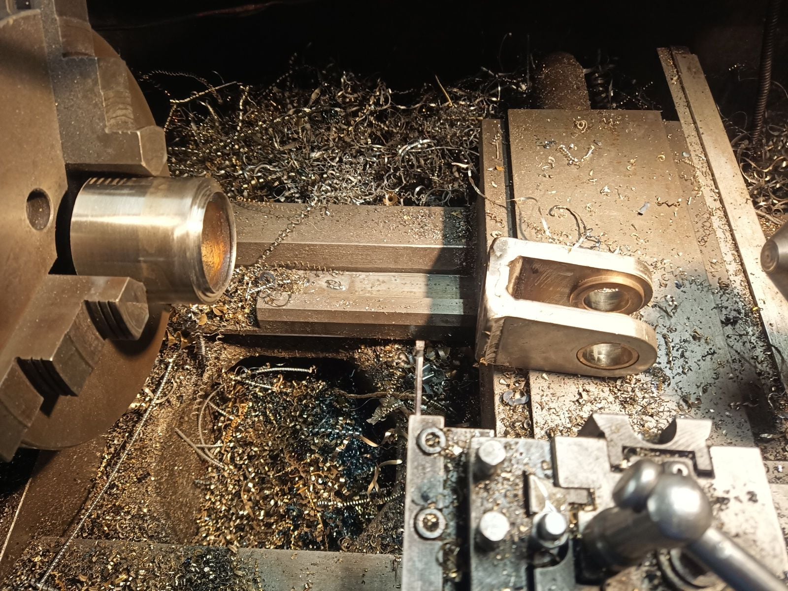
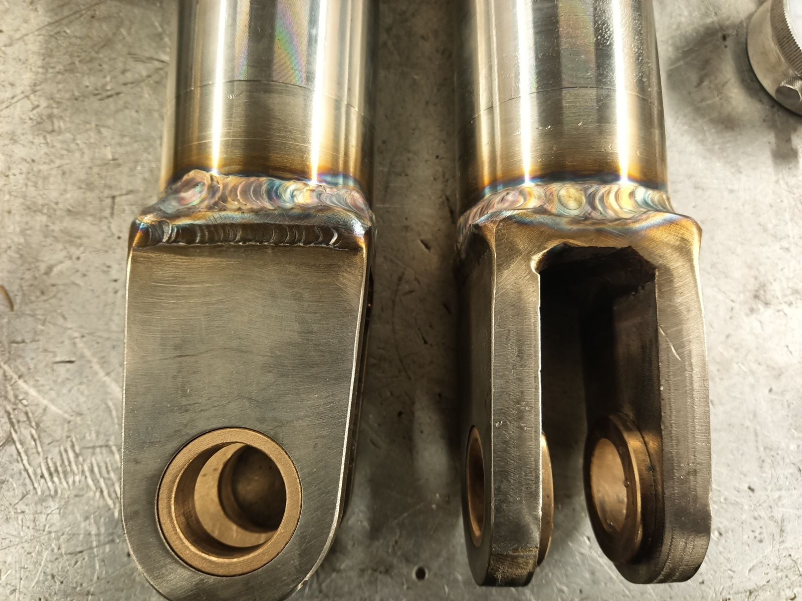
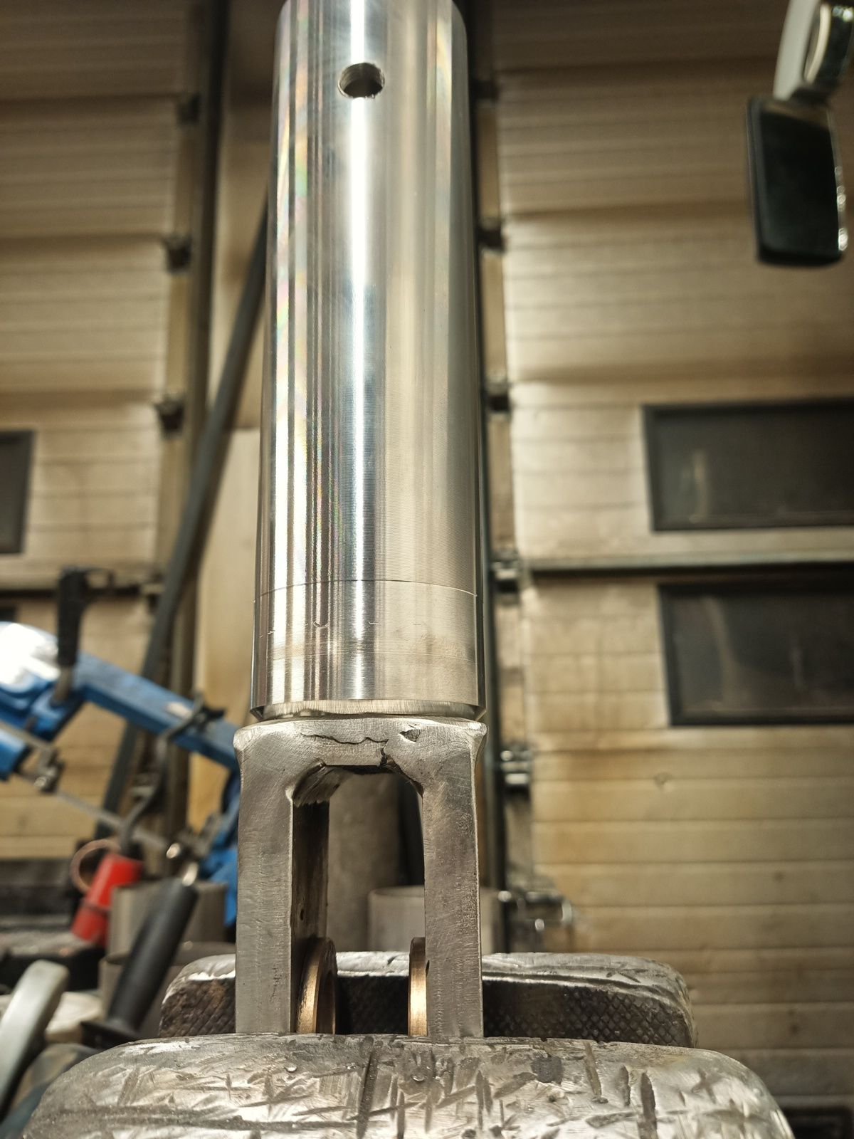
Cylinder upper ball joints are also ready. I hope that welding don't pull threads to ellipse but of course it did, 0.5mm(0.027") ellipse and threaded aluminium bronze races doesn't fit att all!
No worry, I made special tool to press them back to round.
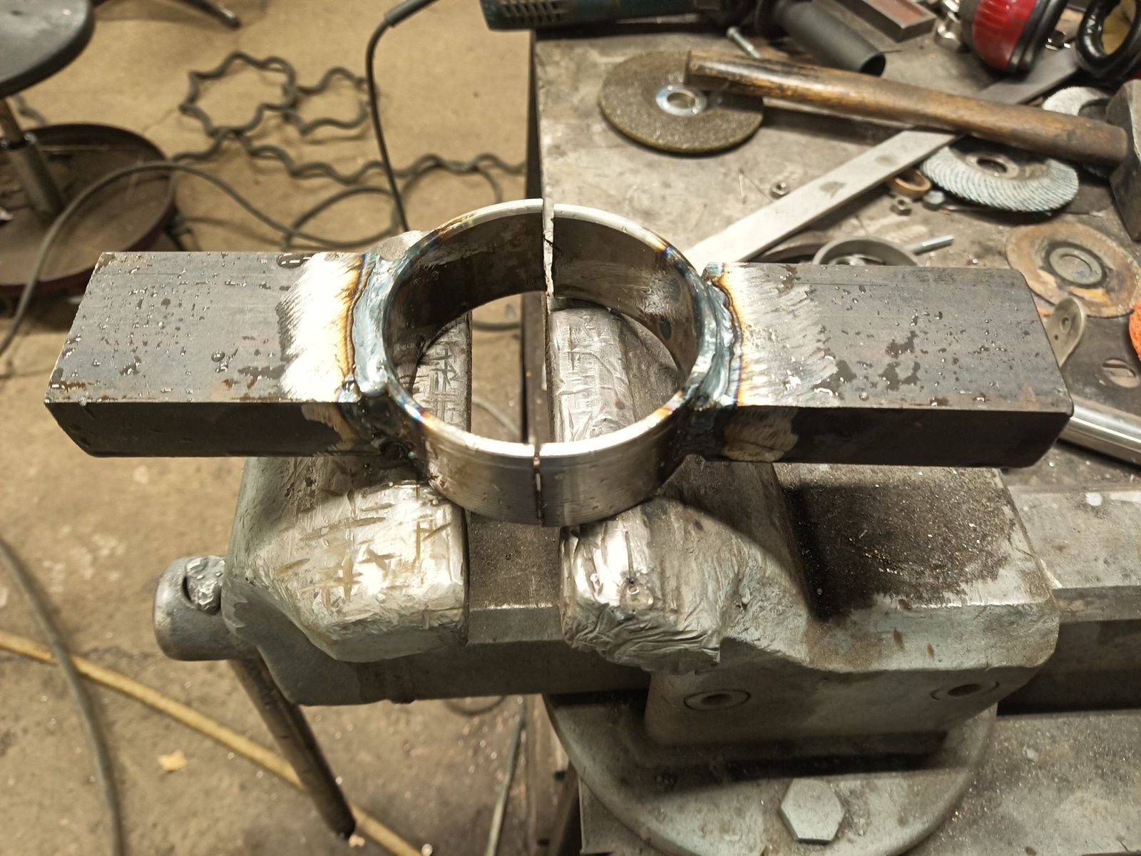
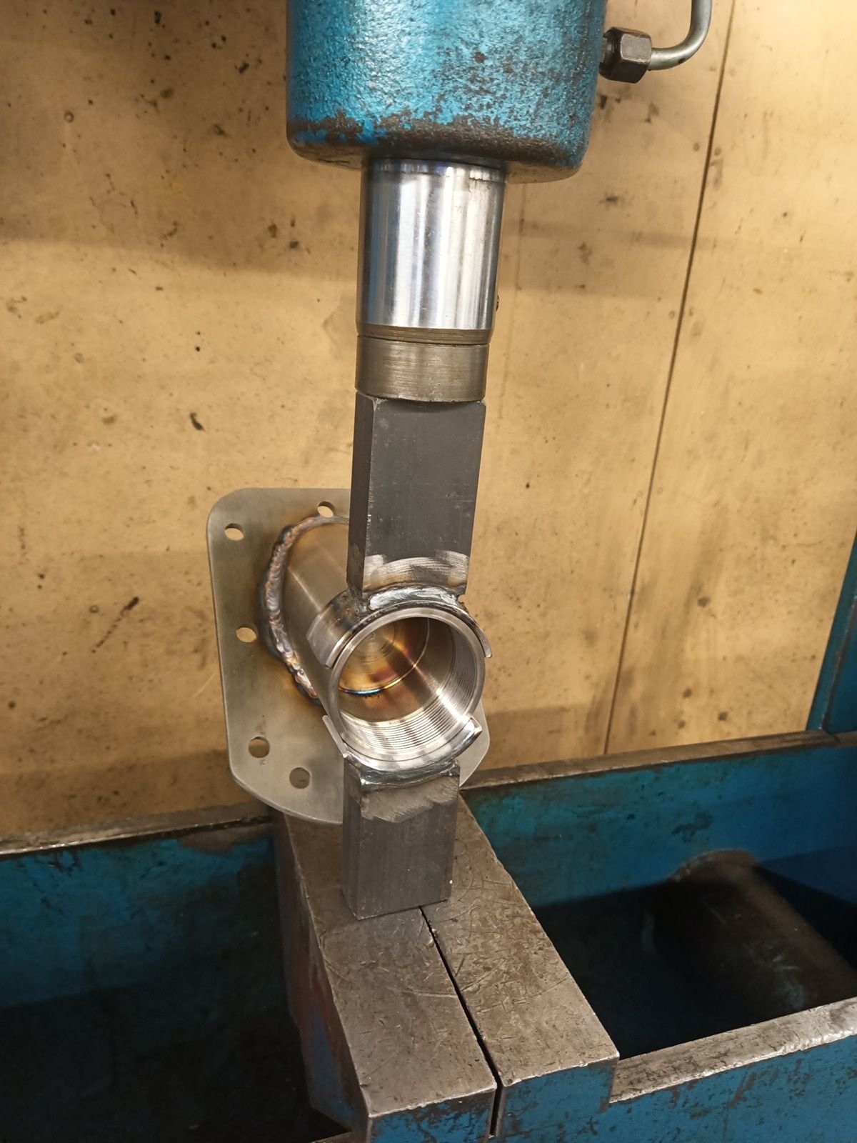
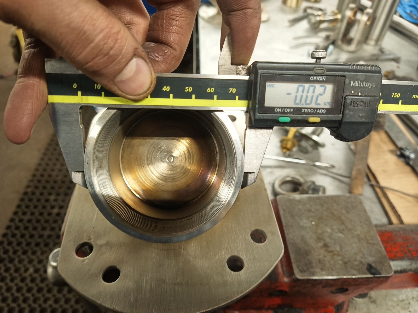
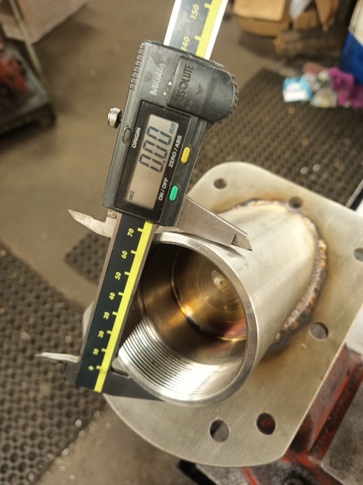
They are now only 0.02mm(0.00079") ellipse, but bronze races doesn't fit after all, there is some other dimension problem.
I recut thread little and now everything work great.
Ball to stem fit was too tight also, they almost seized up before go to right spot. Too much press force will bent cylinder stems but heating helps to lose fit just right.
This time I weld all parts myself.
Cylinder upper ball joints are also ready. I hope that welding don't pull threads to ellipse but of course it did, 0.5mm(0.027") ellipse and threaded aluminium bronze races doesn't fit att all!
No worry, I made special tool to press them back to round.
They are now only 0.02mm(0.00079") ellipse, but bronze races doesn't fit after all, there is some other dimension problem.
I recut thread little and now everything work great.
Ball to stem fit was too tight also, they almost seized up before go to right spot. Too much press force will bent cylinder stems but heating helps to lose fit just right.
The following 4 users liked this post by ksalmine:
02-20-2024, 02:00 PM
#295
Registered
Thread Starter
Two weeks gone after last update and project has gone forward pretty good.
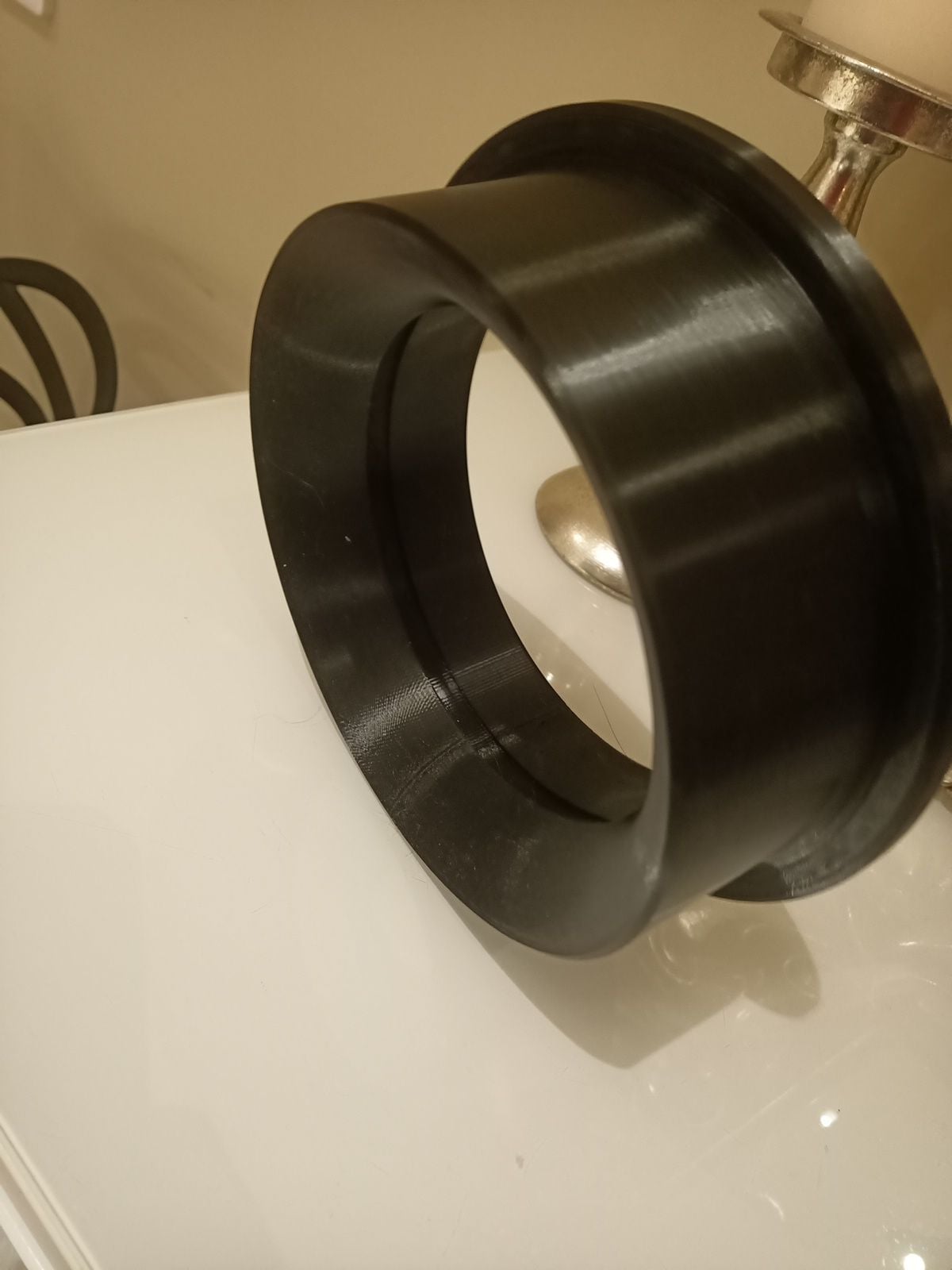
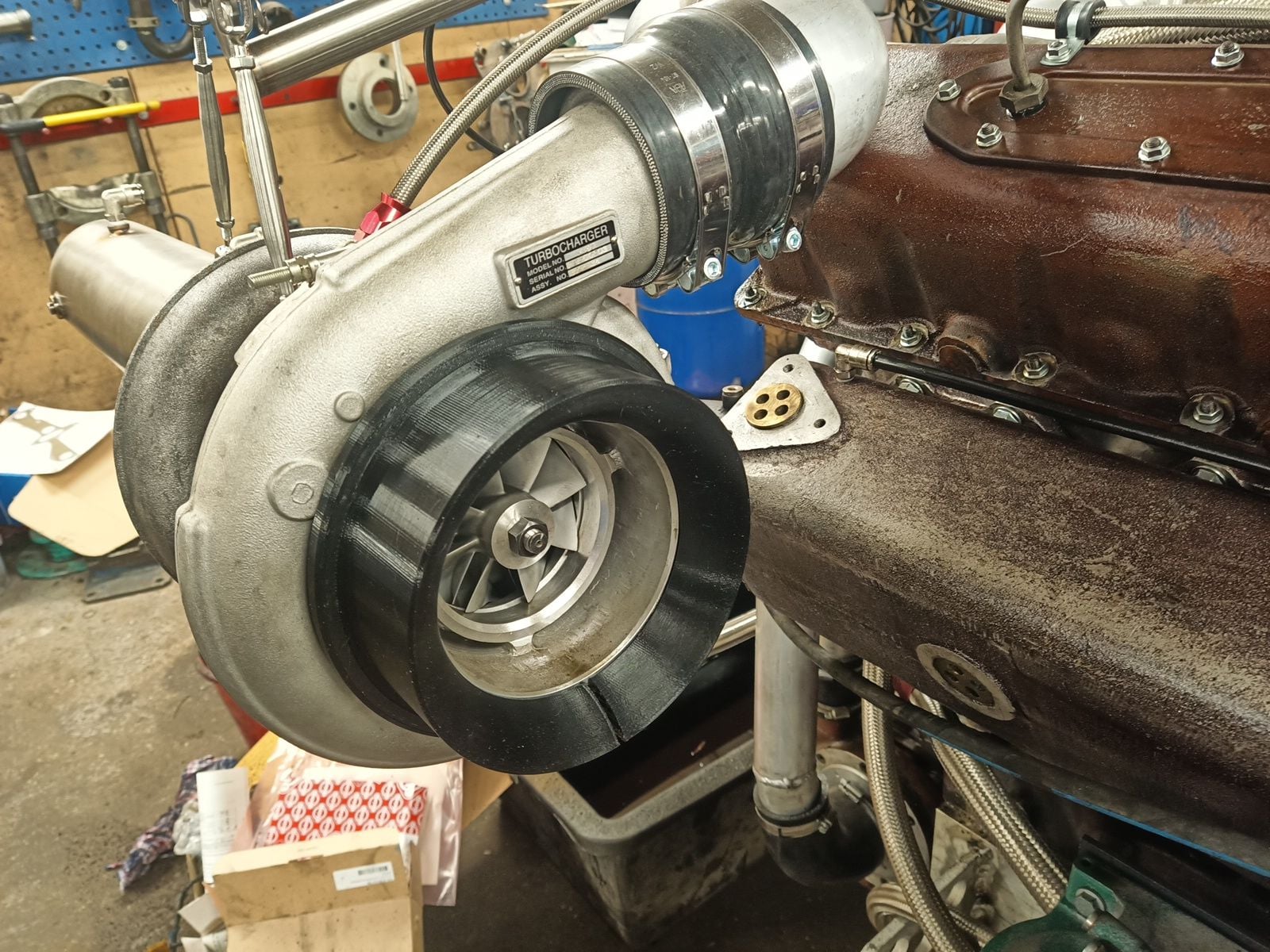
I try new to me manufacturing method, 3D printing. Turbocharger inlet adapter for Scania D16 air filter succeeded well. Front mount that keep filter in place is not ready yet.
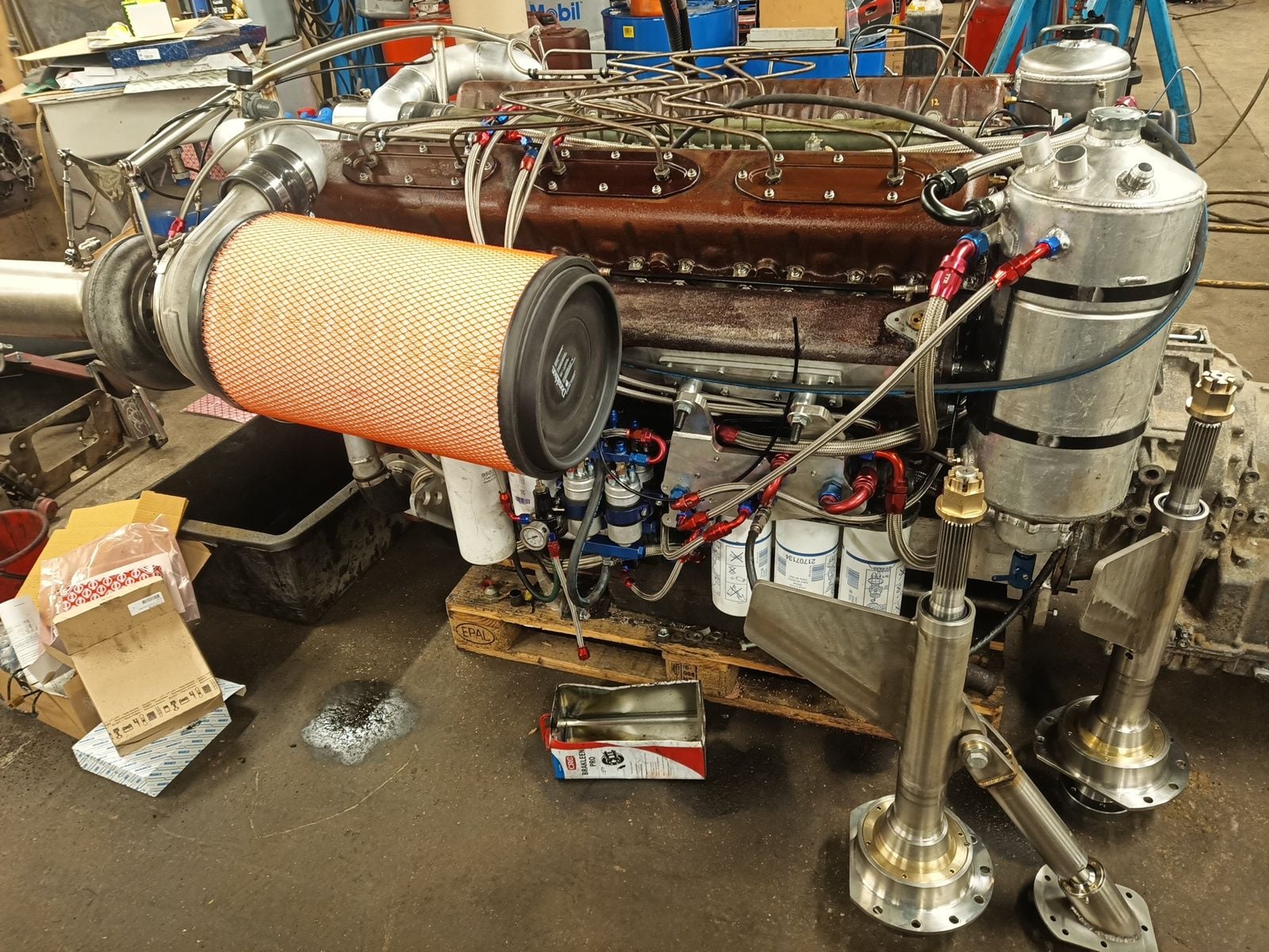
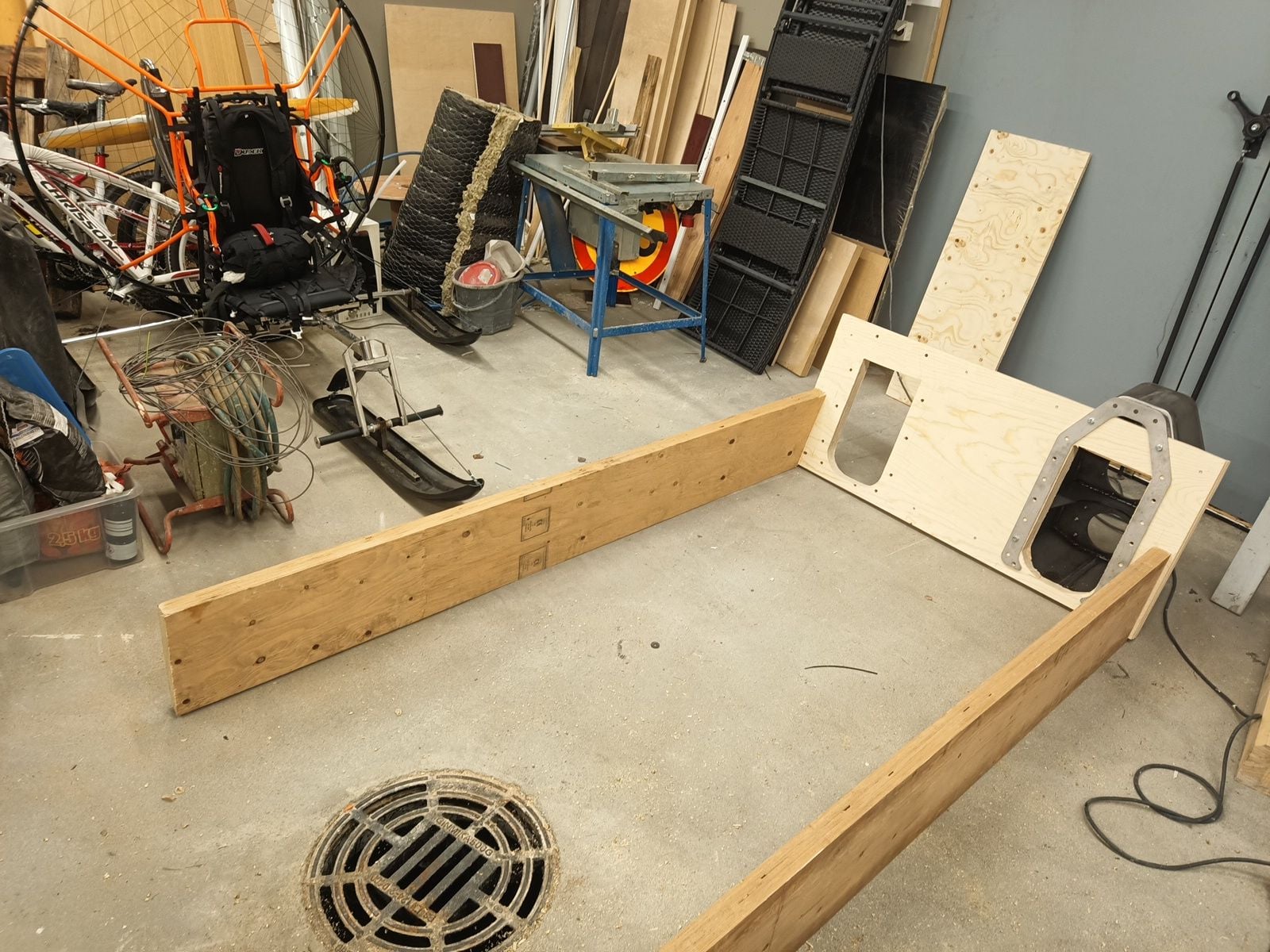
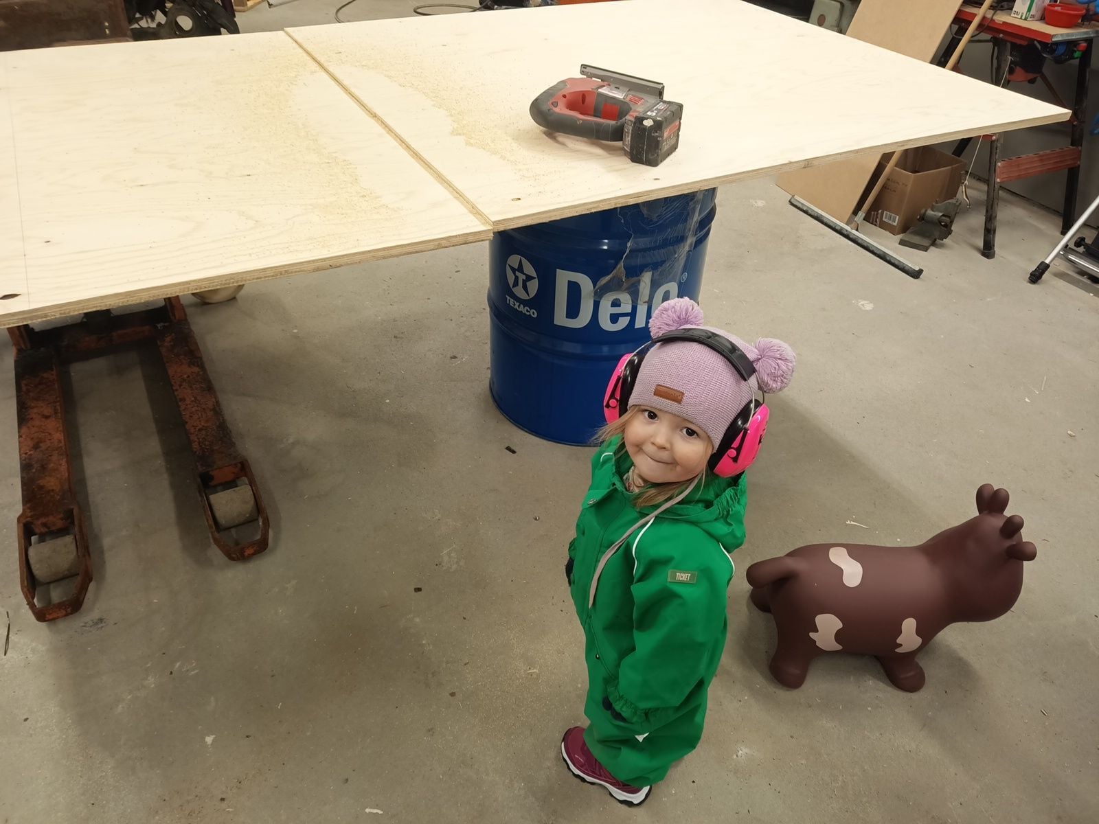
I made boat copy from wood with my little helper girl. She can already give me some tools and screws, maybe after few years I don't need do all myself anymore....
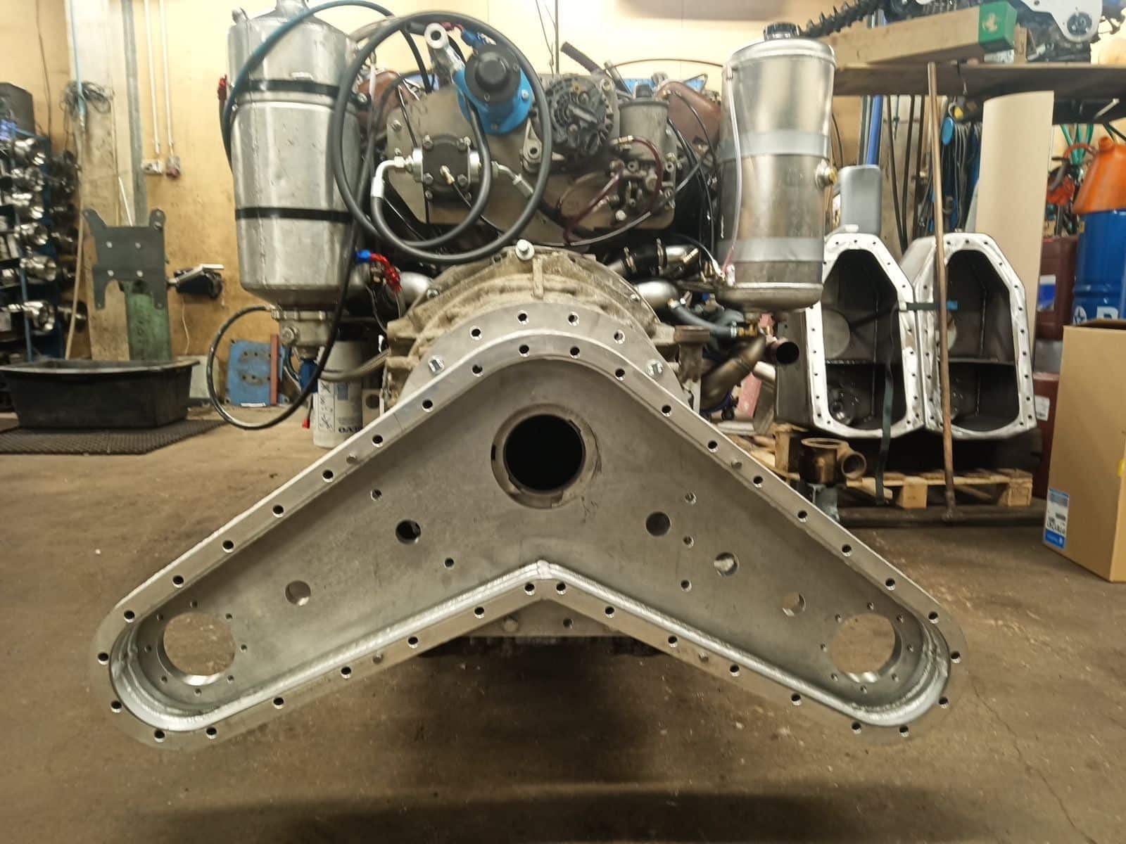
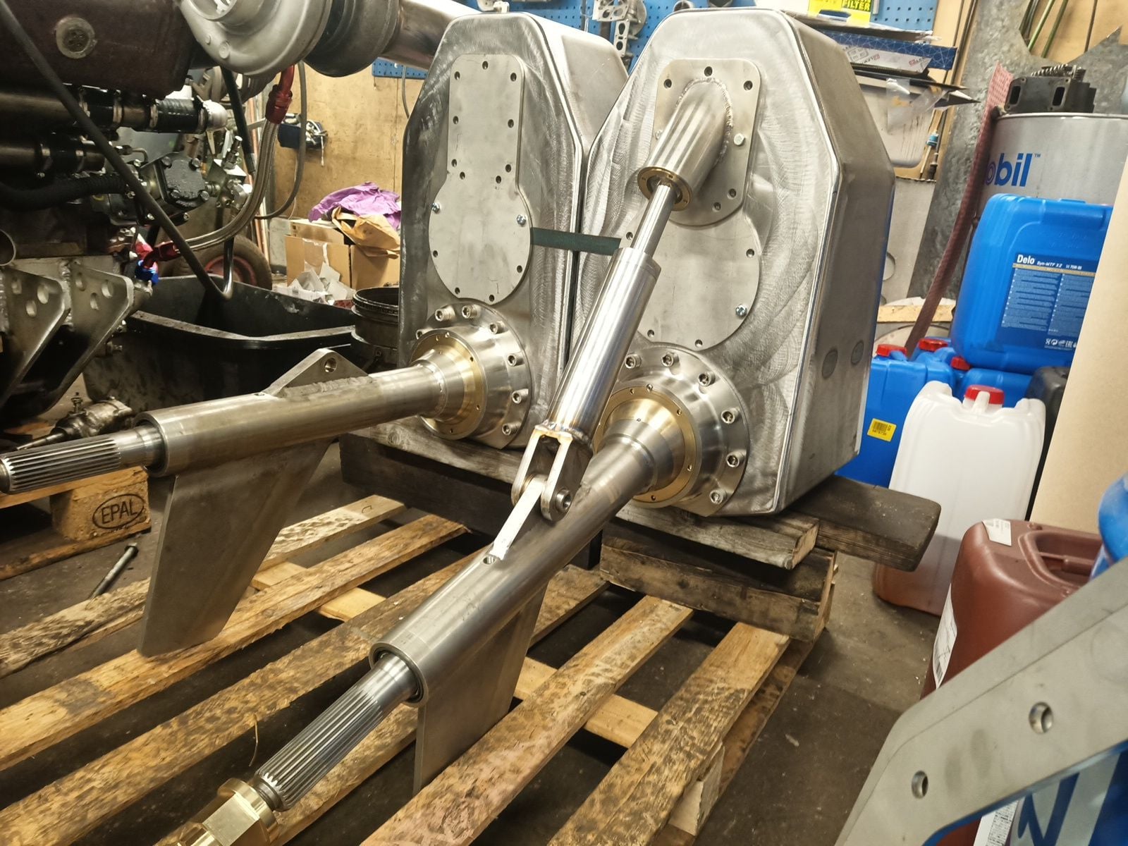
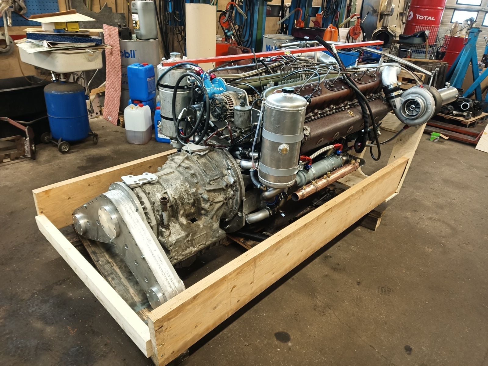
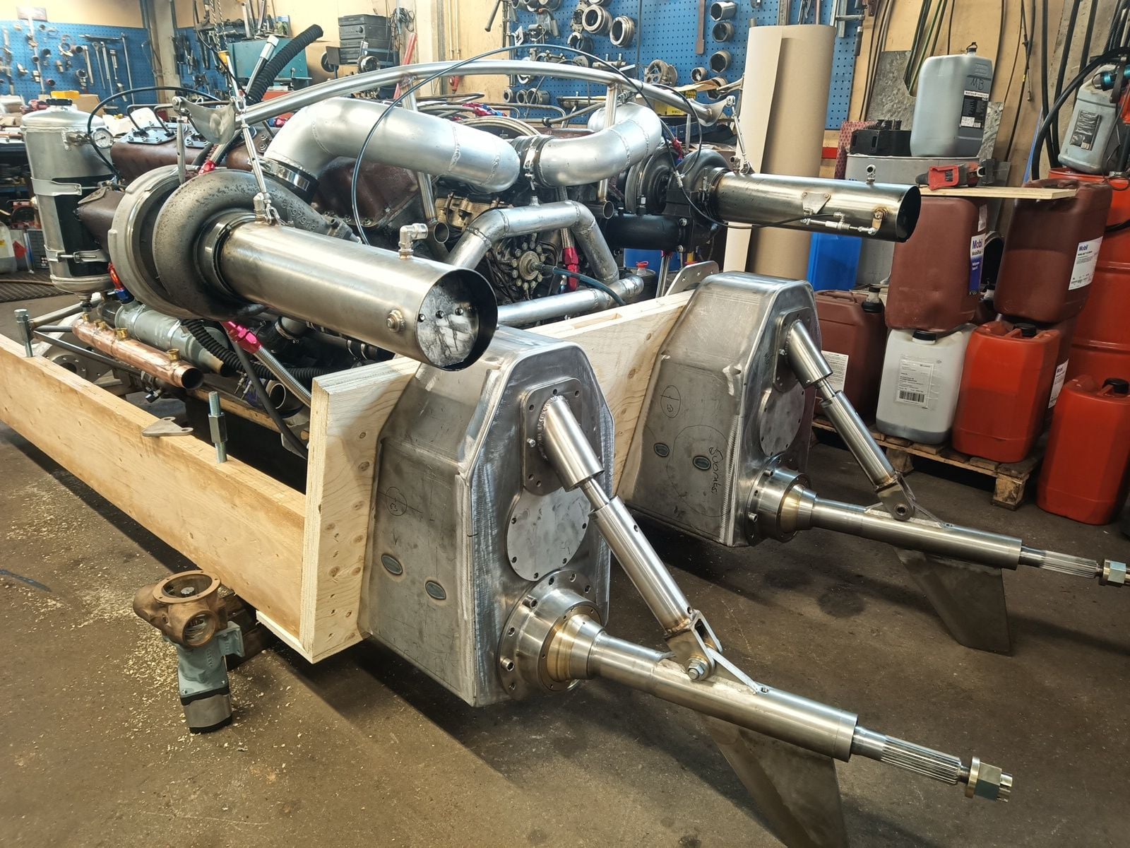
Happy to see powerline as a whole first time! Not only CAD drawings and mental images but real things start take shape.
Wooden copy was first boat project part that was done in my new garage, boat goes there too soon. I think to use it in truck quick wash then lift, drag and jack it in garage, boat have four years dirty on it.
Engine compartment get pretty full, package is so big that only 4" free space longitudinally, sideways is good space. Wooden mock up is accurate copy from transom, notch and future ones stringers. Stringers I tought I would make urethane foam core carbon reinforce glassfiber.
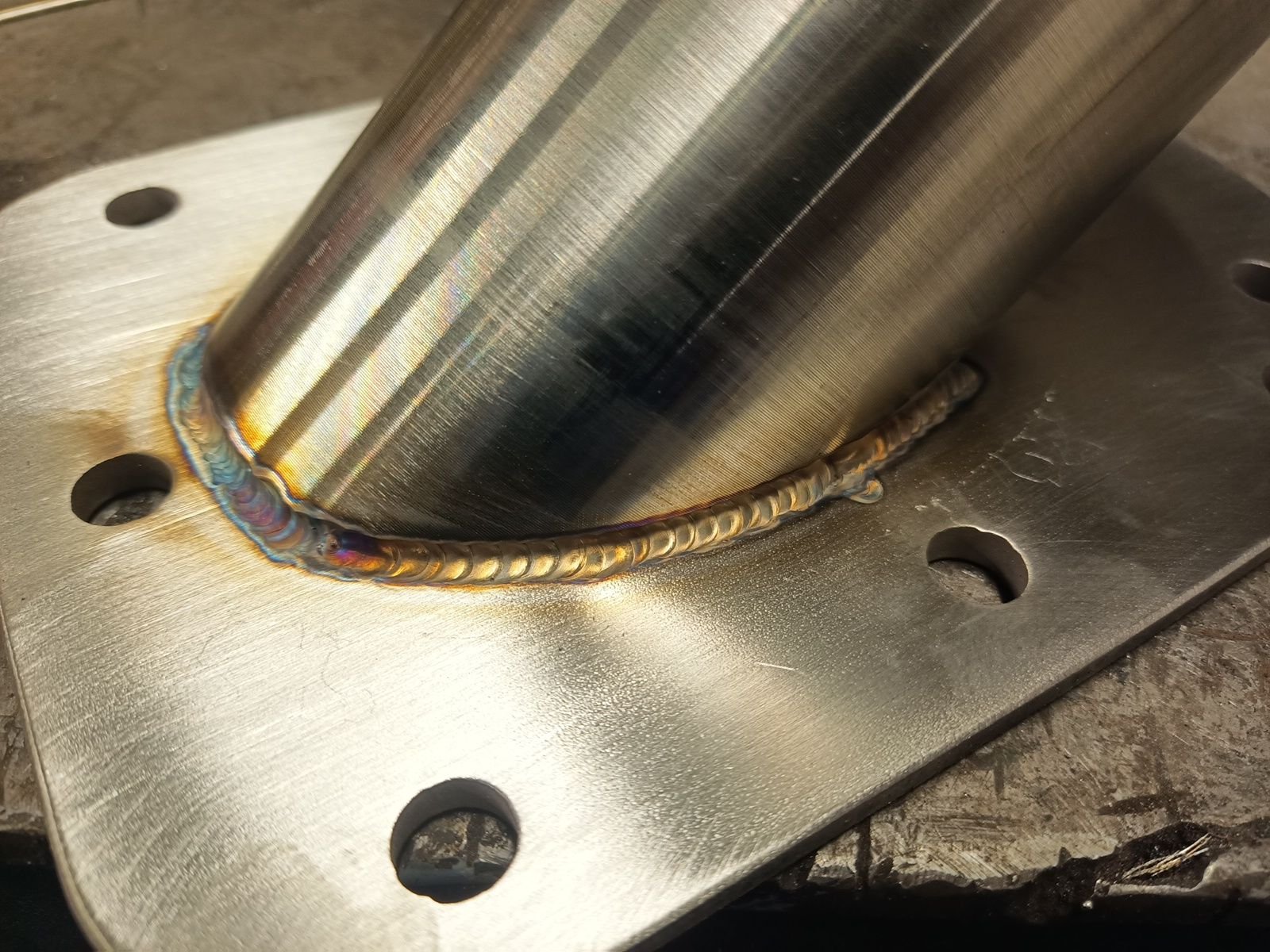
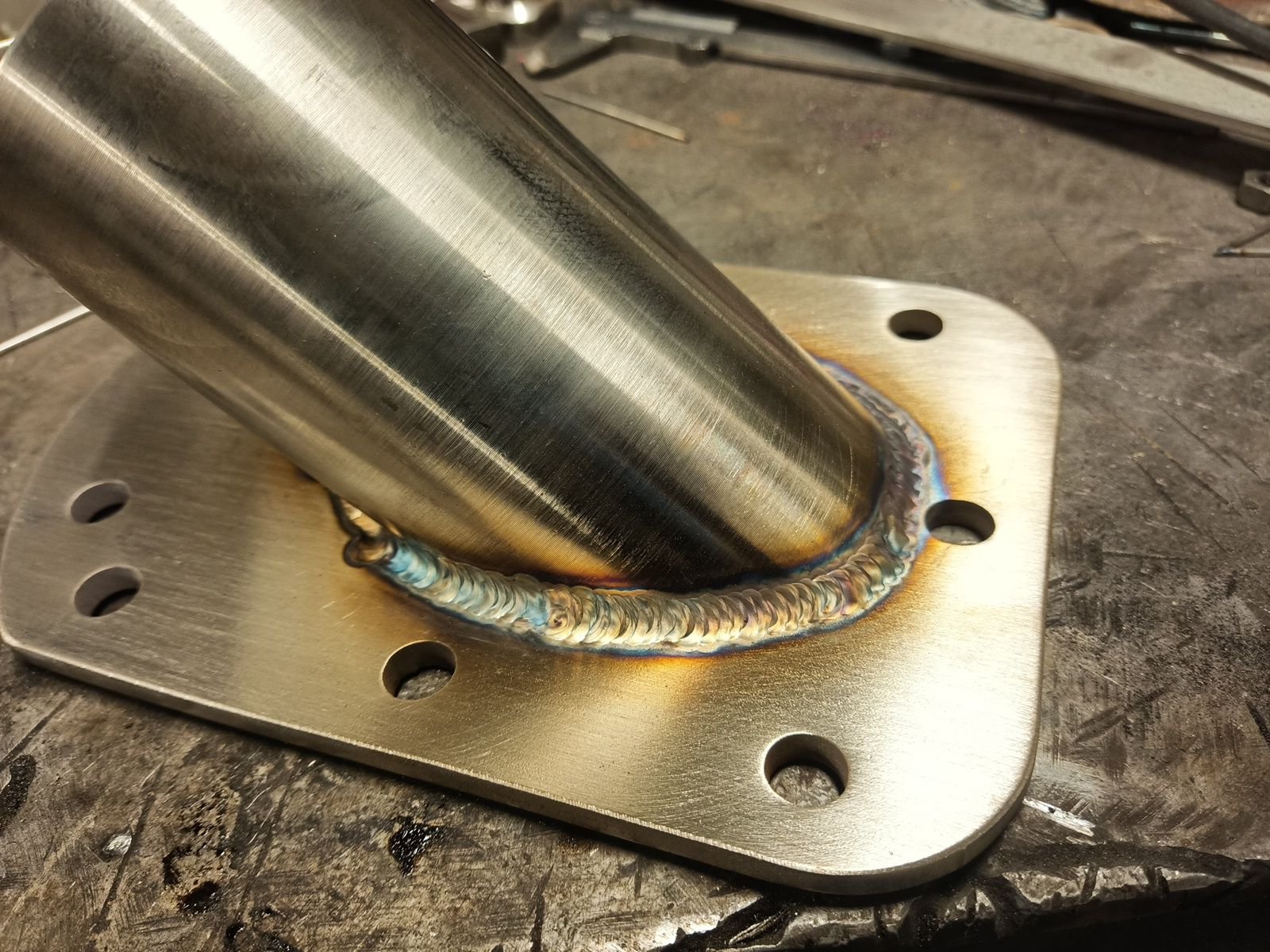
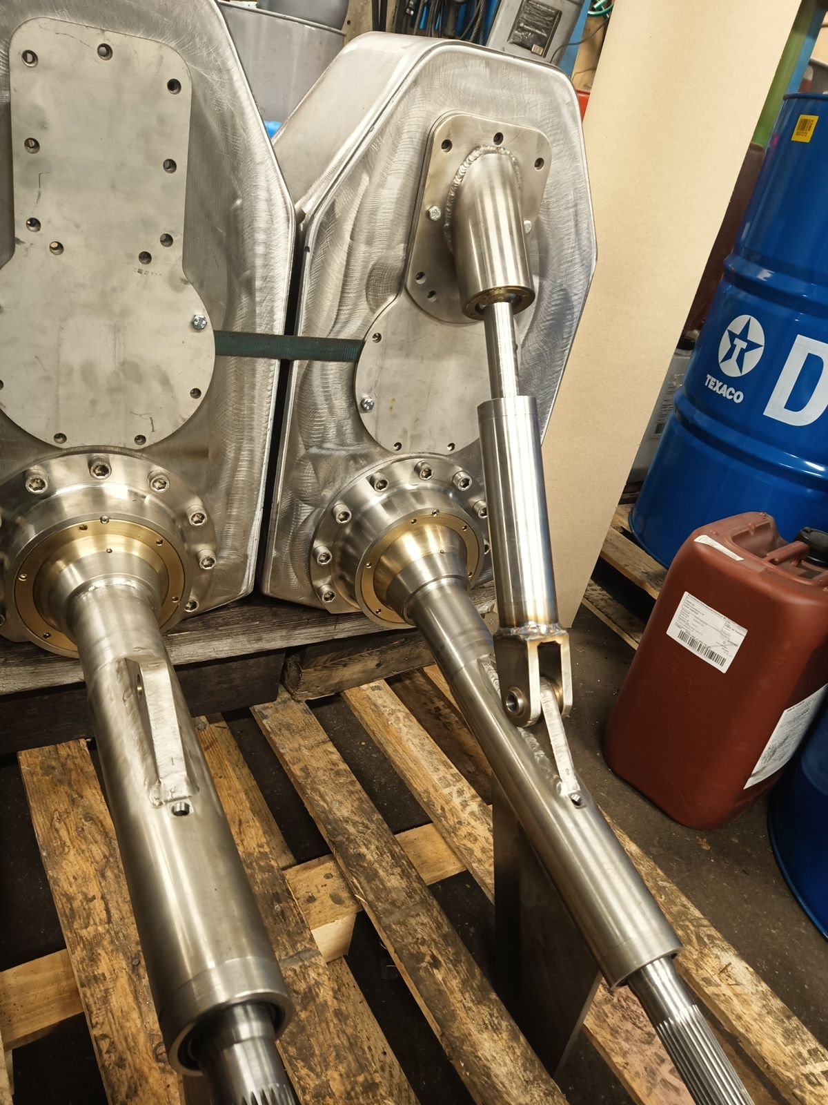
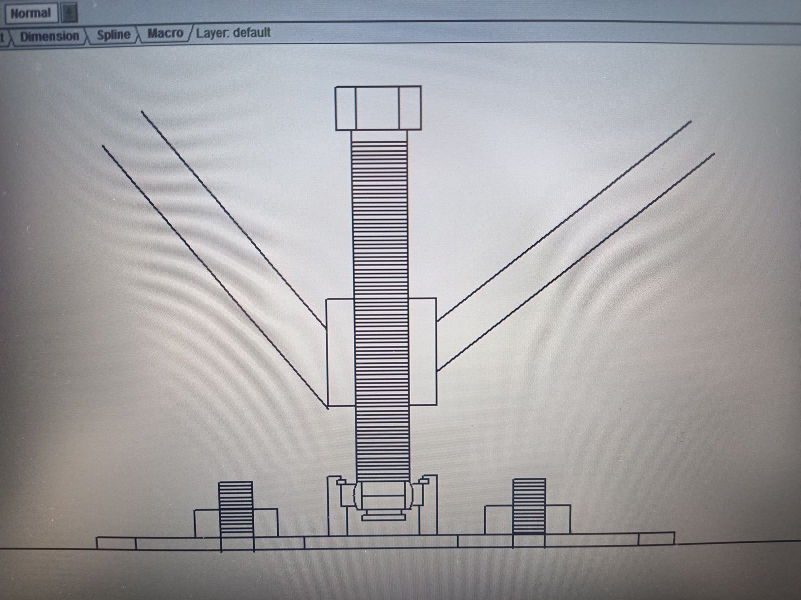
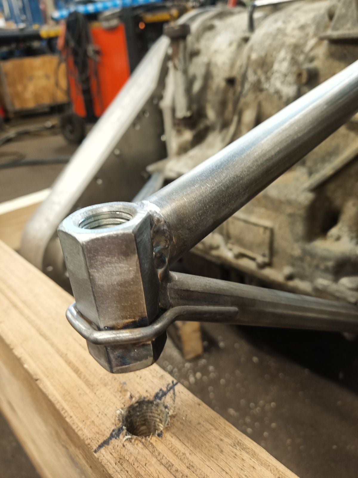
I made tubular engine mounts to save some weight, they came out very light and strong thanks to geometry. All tubes see only pull or push forces, push force tubes are bigger diameter than others to prevent buckling. I weld extra reinforcement to pull side tubes if my welds is not good enough. Engine mounts are solid, no rubber, and they have plenty of height adustment so driveshaft angles can be adjusted as shallow as possible. Longitudial adjustment is must also to get driveshaft lenght right. CV joints will make excessive heat if they are not centered at full power.
Steering cylinders fixed points have to find out next and engineer water pickup for raw water. I hope to get it wet next summer or autumn, let see will it succeed.
I try new to me manufacturing method, 3D printing. Turbocharger inlet adapter for Scania D16 air filter succeeded well. Front mount that keep filter in place is not ready yet.
I made boat copy from wood with my little helper girl. She can already give me some tools and screws, maybe after few years I don't need do all myself anymore....
Happy to see powerline as a whole first time! Not only CAD drawings and mental images but real things start take shape.
Wooden copy was first boat project part that was done in my new garage, boat goes there too soon. I think to use it in truck quick wash then lift, drag and jack it in garage, boat have four years dirty on it.
Engine compartment get pretty full, package is so big that only 4" free space longitudinally, sideways is good space. Wooden mock up is accurate copy from transom, notch and future ones stringers. Stringers I tought I would make urethane foam core carbon reinforce glassfiber.
I made tubular engine mounts to save some weight, they came out very light and strong thanks to geometry. All tubes see only pull or push forces, push force tubes are bigger diameter than others to prevent buckling. I weld extra reinforcement to pull side tubes if my welds is not good enough. Engine mounts are solid, no rubber, and they have plenty of height adustment so driveshaft angles can be adjusted as shallow as possible. Longitudial adjustment is must also to get driveshaft lenght right. CV joints will make excessive heat if they are not centered at full power.
Steering cylinders fixed points have to find out next and engineer water pickup for raw water. I hope to get it wet next summer or autumn, let see will it succeed.
The following 7 users liked this post by ksalmine:
AllDodge (02-20-2024), IGetWet (02-20-2024), rak rua (02-20-2024), RSCHAP1 (02-21-2024), Sydwayz (02-21-2024), thegoodson (02-20-2024), Twin O/B Sonic (02-21-2024)
02-20-2024, 02:05 PM
#296
Registered
Thread Starter
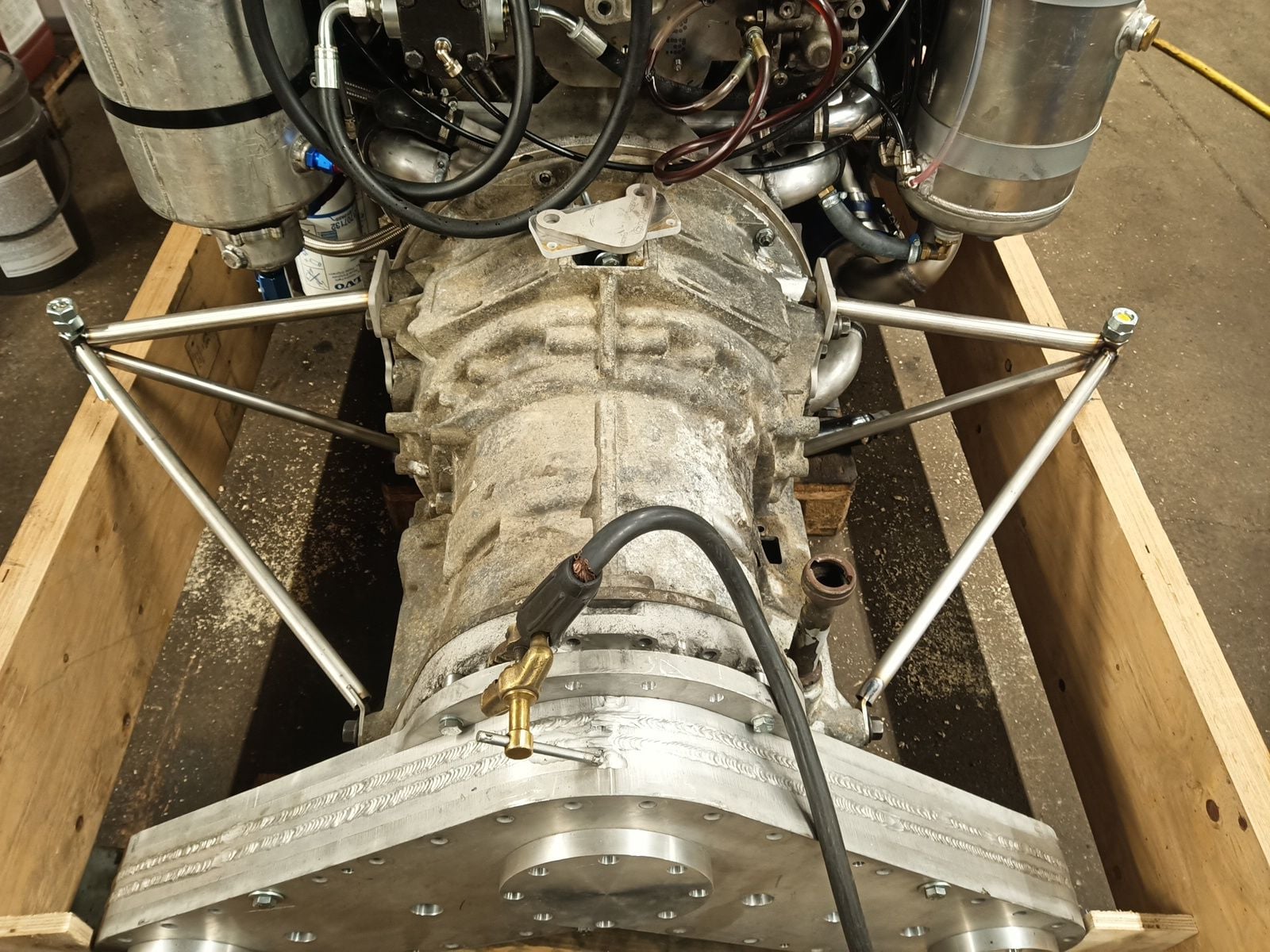
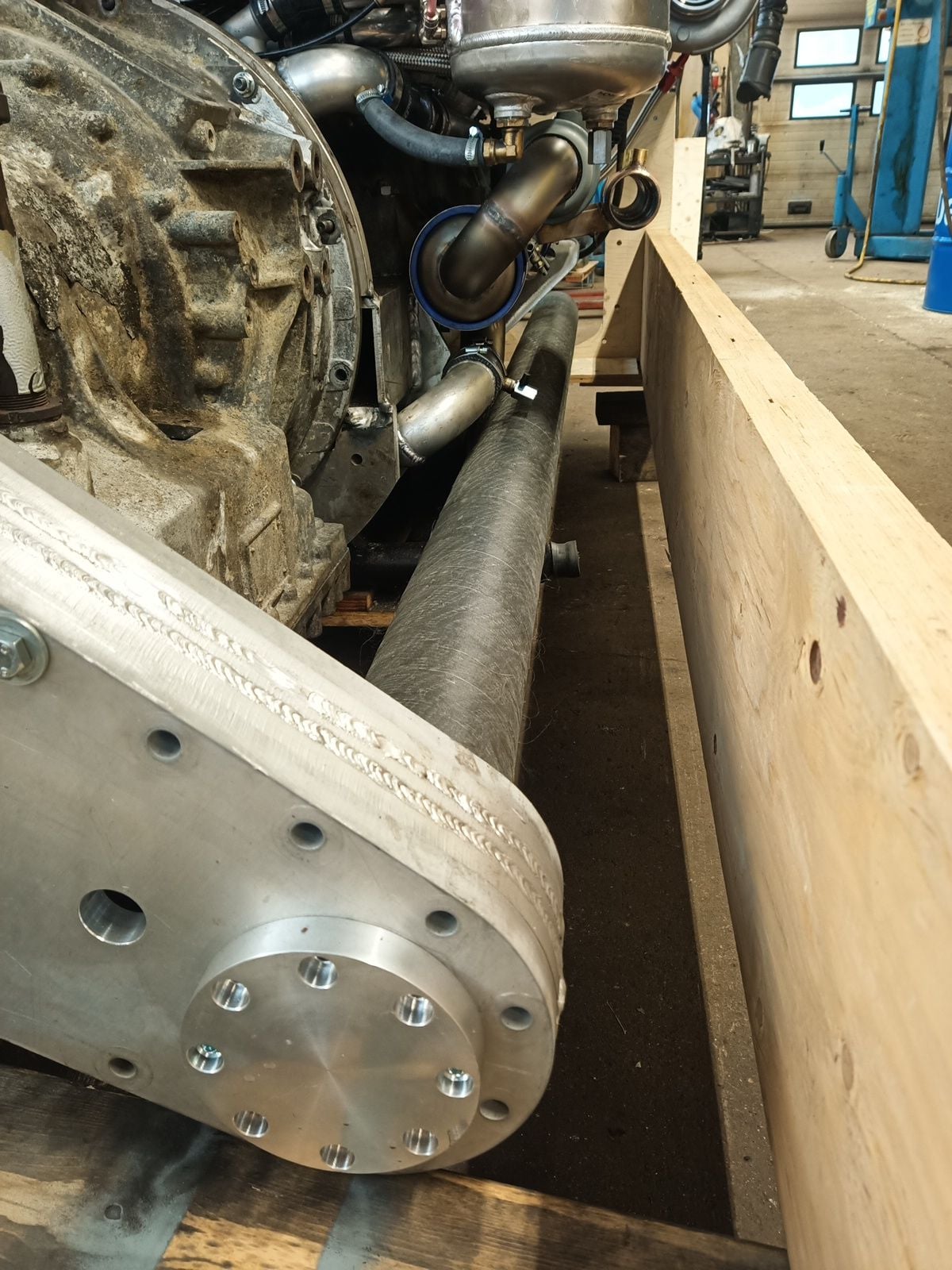
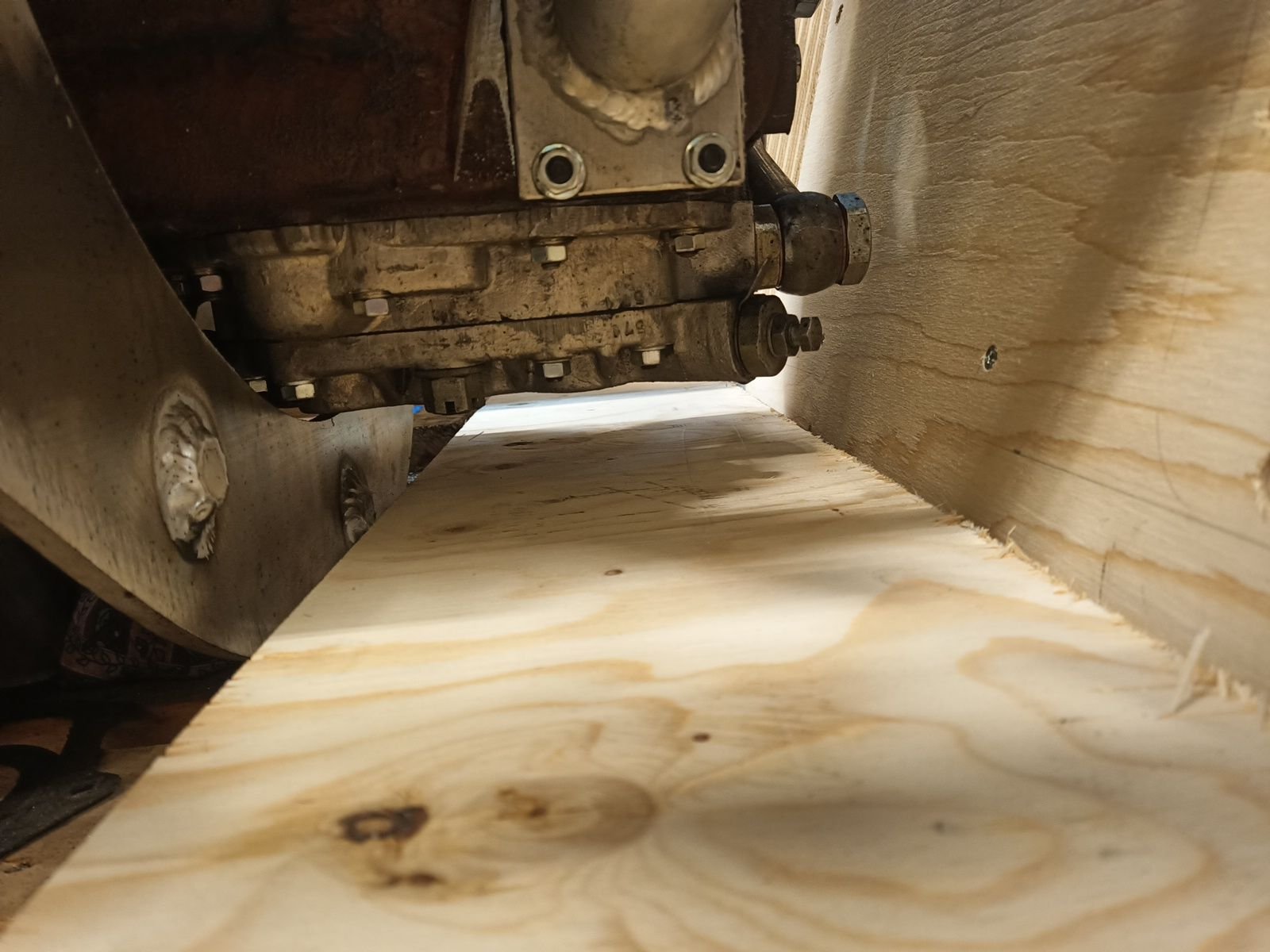
I forgot to show how well engine goes in place. Drysump pump to notch clearance is nice so engine sit as low as possible in boat. Carbon driveshafts have also clear route from splitbox to drives. Coolant drain valve is scary close but shafts will go lower in boat. Wooden mock up transom is not grind to real shape yet.
The following 4 users liked this post by ksalmine:
02-21-2024, 05:47 AM
#297
Registered
Great progress and I always looks forward to updates. Thanks for keeping it up!
Am I the only one that just realized the transmission and split box are going to be in front of the engine?
Am I the only one that just realized the transmission and split box are going to be in front of the engine?
The following 2 users liked this post by jadento:
Quinlan (02-21-2024), Twin O/B Sonic (02-21-2024)
02-21-2024, 06:07 AM
#298
Registered
Two weeks gone after last update and project has gone forward pretty good.
I try new to me manufacturing method, 3D printing. Turbocharger inlet adapter for Scania D16 air filter succeeded well. Front mount that keep filter in place is not ready yet.
I made boat copy from wood with my little helper girl. She can already give me some tools and screws, maybe after few years I don't need do all myself anymore....
Happy to see powerline as a whole first time! Not only CAD drawings and mental images but real things start take shape.
Wooden copy was first boat project part that was done in my new garage, boat goes there too soon. I think to use it in truck quick wash then lift, drag and jack it in garage, boat have four years dirty on it.
Engine compartment get pretty full, package is so big that only 4" free space longitudinally, sideways is good space. Wooden mock up is accurate copy from transom, notch and future ones stringers. Stringers I tought I would make urethane foam core carbon reinforce glassfiber.
I made tubular engine mounts to save some weight, they came out very light and strong thanks to geometry. All tubes see only pull or push forces, push force tubes are bigger diameter than others to prevent buckling. I weld extra reinforcement to pull side tubes if my welds is not good enough. Engine mounts are solid, no rubber, and they have plenty of height adustment so driveshaft angles can be adjusted as shallow as possible. Longitudial adjustment is must also to get driveshaft lenght right. CV joints will make excessive heat if they are not centered at full power.
Steering cylinders fixed points have to find out next and engineer water pickup for raw water. I hope to get it wet next summer or autumn, let see will it succeed.
Also I’m not sure what kind of printer you have, but I can print parts stronger than 6061 AL if you come across anything you might need where strength is critical. Also extremely accurate. Continuous carbon fiber, or kevlar, or fiberglass reinforced nylon. I’d be happy to contribute.
Last edited by IGetWet; 02-21-2024 at 06:14 AM.
02-21-2024, 06:25 AM
#299
Registered
So basically, it's a V Drive. Love it.

